Vehicular navigation based on site specific sensor quality data

a sensor quality and vehicle technology, applied in vehicle position/course/altitude control, process and machine control, instruments, etc., can solve the problems of odometer to estimate, many location sensing devices subject to material errors, odometer to be used

Active Publication Date: 2006-08-24
DEERE & CO
View PDF8 Cites 33 Cited by
  • Summary
  • Abstract
  • Description
  • Claims
  • Application Information

AI Technical Summary

Benefits of technology

The invention relates to an improved way to locate vehicles accurately by analyzing their position inside different areas or cells during operation. This helps improve efficiency and accuracy when managing traffic flow.

Problems solved by technology

This patented describes how locating sensor technology can be affected due to factors like incorrect measurements caused by slip on surfaces such as roads during construction activities that require precise knowledge about where things stand out nearby. There needs improvement if current methods cannot provide reliable results when used without these issues being addressed.

Method used


Image

  • Vehicular navigation based on site specific sensor quality data
  • Vehicular navigation based on site specific sensor quality data
  • Vehicular navigation based on site specific sensor quality data

Examples


Embodiment Construction

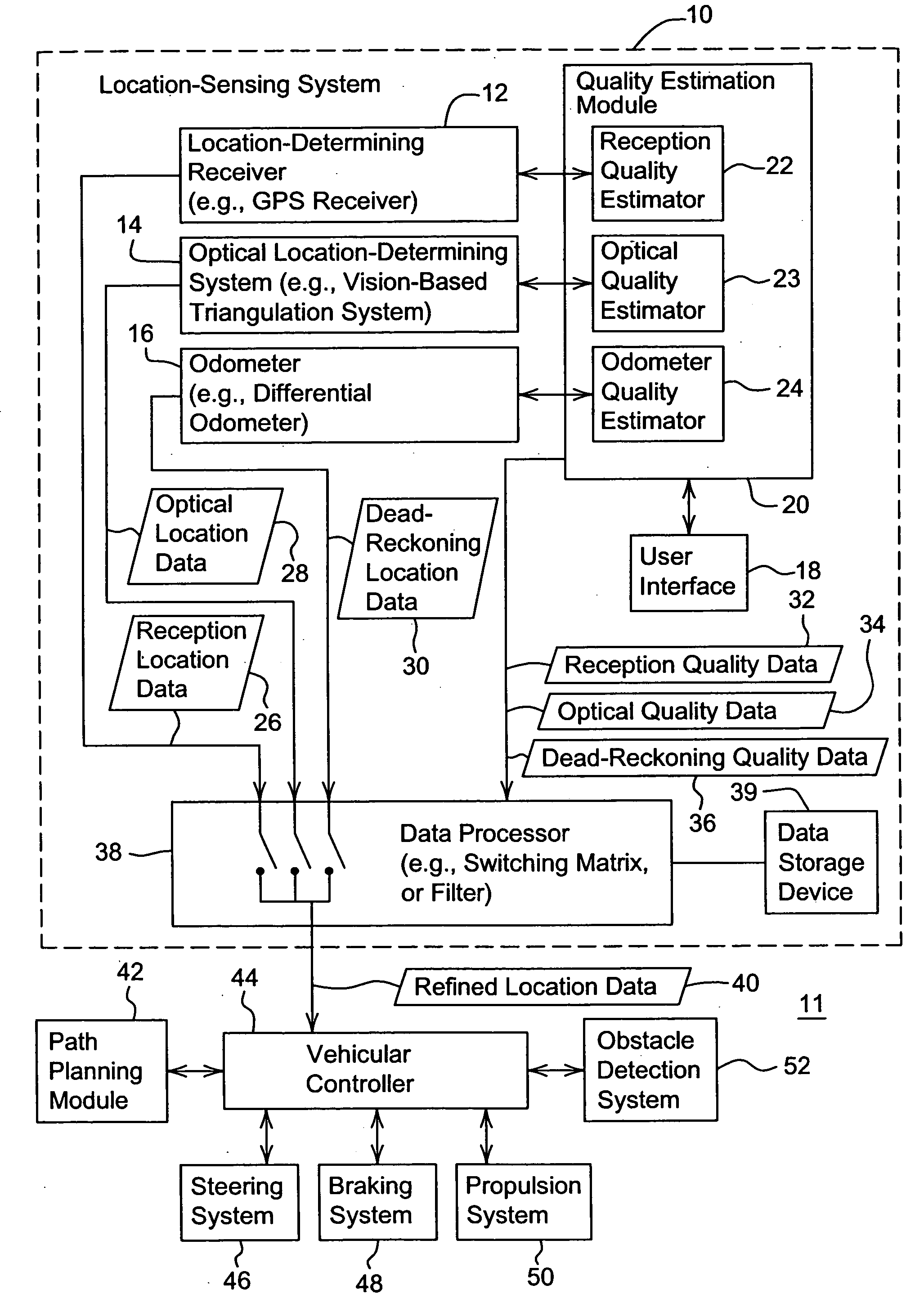
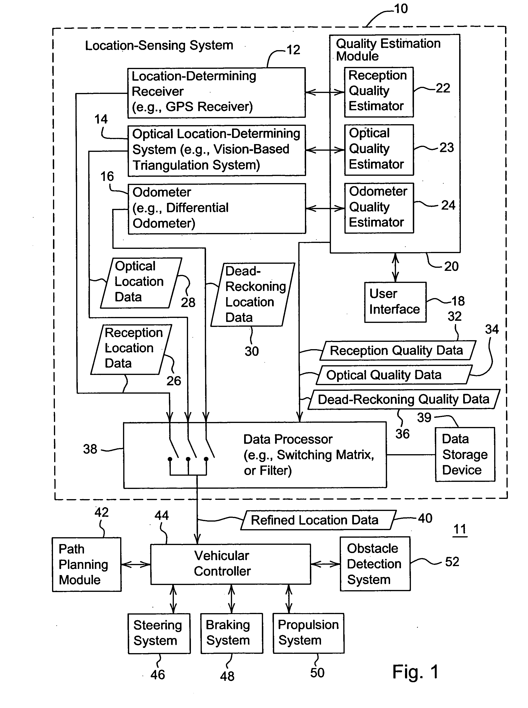
[0016] In accordance with one embodiment, FIG. 1 shows a system 11 for determining a location of a vehicle based on site specific sensor quality data. The system 11 comprises a location-sensing system 10 coupled to a vehicular controller 44. A path planning module 42 may provide a path plan or other navigation-related input data to the vehicular controller 44. The obstacle detection system 52 may provide navigation-related input on stationary or moving objects within a work area (e.g., to avoid collisions with such objects). In turn, the vehicular controller 44 may communicate with (e.g., issue control data or signals to) one or more of the following: a steering system 46, a braking system 48, and a propulsion system 50.

[0017] In one embodiment, the location sensing system 10 comprises a location-determining receiver 12, an optical location determining system 14, and a dead-reckoning system 16 that are coupled to a quality estimation module 20. The location determining receiver 12, th


PUM


Abstract

A method and system for determining a location of a vehicle, the method comprises determining reception location data within a first cell of a work area for a vehicle. A reception quality estimator estimates reception quality data for the corresponding reception location data for the first cell. Optical location data is determined within a first cell of a work area for a vehicle. An optical quality estimator estimates optical quality data for the corresponding optical location data for the first cell. A data processor selects at least one of the reception location data and the optical location data as refined location data associated with the first cell based on the estimated reception quality data and estimated optical quality data.

Description


Claims


Application Information

Patent Timeline
Owner DEERE & CO
Why Eureka
Try Eureka