Compressor output calculation unit and control unit using the same

A computing unit and compressor technology, applied in engine control, pump control, transportation and packaging, etc., can solve problems such as refrigerant circuit pressure loss, and achieve the effect of simplifying the system

Inactive Publication Date: 2005-02-02
SANDEN CORP
View PDF2 Cites 8 Cited by
  • Summary
  • Abstract
  • Description
  • Claims
  • Application Information

AI Technical Summary

Benefits of technology

The technical effect described in this patented design allows for more efficient use of expensive materials while reducing costs compared with traditional methods like calculating compression force or controller parameters based on temperature alone without sensors.

Problems solved by technology

This patented technology describes various methods that are applied during determining the amount (torsional force) required at each point along different points within a redox cycle. These techniques involve measuring changes over time due to factors like temperature variations and pressures. Additionally, these measurements require expensive equipment which increases costs compared to existing systems.

Method used


Image

  • Compressor output calculation unit and control unit using the same
  • Compressor output calculation unit and control unit using the same
  • Compressor output calculation unit and control unit using the same

Examples


Embodiment Construction

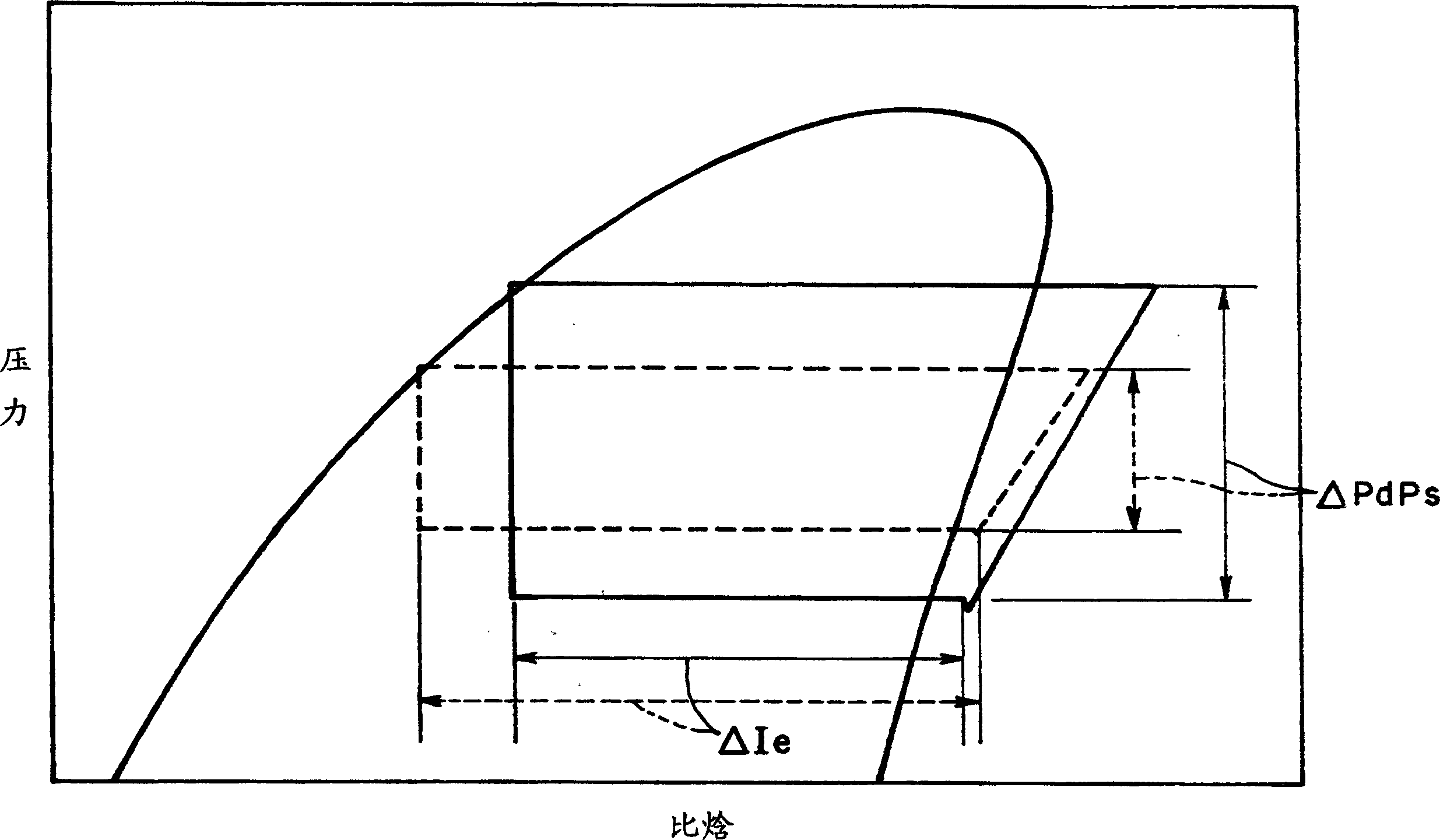
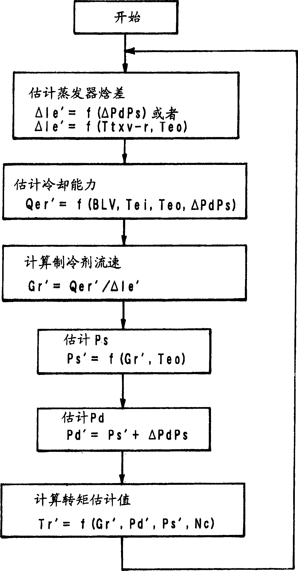
[0049] figure 1 An air conditioning system for a vehicle having a compressor output calculation unit according to an embodiment of the present invention is described. The refrigeration circuit 1 has a variable displacement compressor that can control the discharge amount of refrigerant or a variable displacement compressor 2 that can control the pressure difference between the discharge pressure and the suction pressure. The engine drives, and the driving force of the engine is transmitted via an electromagnetic clutch included in the compressor 2 . The refrigerant circulates in the refrigerant circuit of the refrigeration circuit 1, and the high-temperature and high-pressure refrigerant compressed by the compressor 2 is cooled at the condenser 3 by exchanging heat with the outside air, and condensed and liquefied. The refrigerant under the two-phase condition of gas and liquid is separated into a gas phase and a liquid phase by the receiver drier 4, and the liquid refrigerant i


PUM


Abstract

A compressor output calculation unit having a variable displacement compressor, a condenser, a pressure reducing mechanism and an evaporator, wherein a compressor torque or power is calculated based on a detected or estimated value of a refrigerant flow rate, a detected or estimated value of a refrigerant discharge pressure, a detected or estimated value of a refrigerant suction pressure, and a compressor rotational speed, and a control unit using the same. The compressor torque or power may be estimated at a high accuracy without using a refrigerant flow sensor.

Description


Claims


Application Information

Patent Timeline
Owner SANDEN CORP
Why Eureka
Try Eureka