Exhaustor for kitchen

A technology for range hoods and kitchens, which is applied in the direction of removing oil fumes, applications, household stoves, etc., and can solve the problems of increased noise and inconvenience for users of range hoods

Inactive Publication Date: 2006-03-29
LG ELECTRONICS (TIANJIN) APPLIANCES CO LTD
View PDF0 Cites 3 Cited by
  • Summary
  • Abstract
  • Description
  • Claims
  • Application Information

AI Technical Summary

Problems solved by technology

However, the discharge noise from the narrow slot of the range hood c

Method used


Image

  • Exhaustor for kitchen
  • Exhaustor for kitchen
  • Exhaustor for kitchen

Examples


Embodiment Construction

[0019] The kitchen range hood of the present invention is described in detail below with reference to the accompanying drawings:

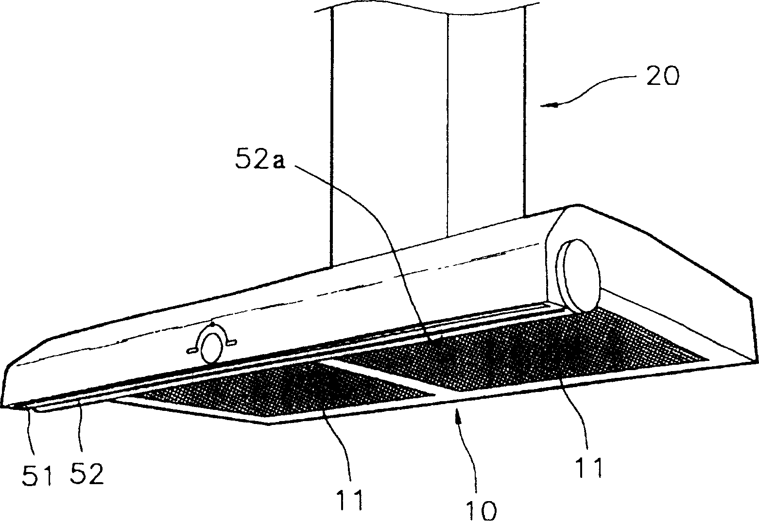
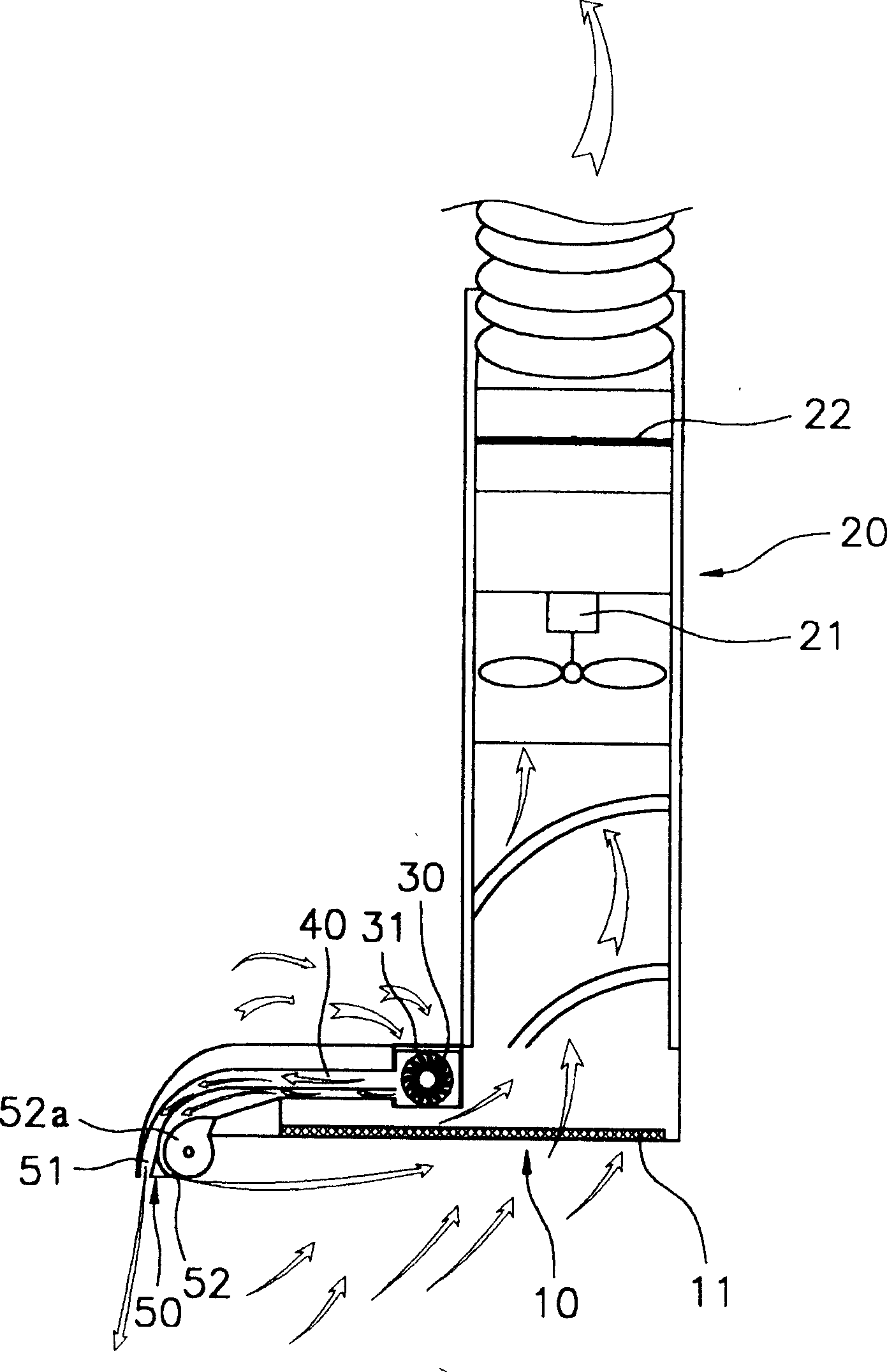
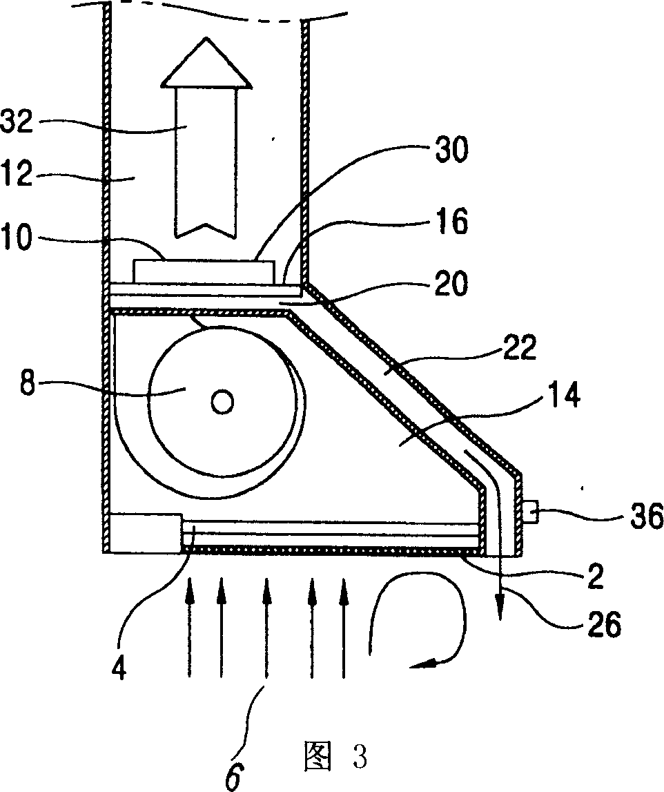
[0020] Such as Figure 4 As shown, it includes a vertical exhaust duct 100 arranged on the ceiling to discharge indoor air upwards, and a horizontal exhaust duct 110 formed at the bottom of the vertical exhaust duct 100, which is connected as a whole and enlarged, is arranged on the vertical exhaust duct 100 Inside, the exhaust fan 200 that sucks in indoor air and discharges it upwards is formed on the inside of the horizontal exhaust duct 110, and the air supply path 140 that sucks the air in the kitchen to the bottom of the exhaust fan 200 is formed on the discharge side of the air supply path 140. The nozzle part 141 and the curved surface part 142 through which the room air passes through the nozzle part 141 suck the polluted air from the air supply path 140 and supply air to the air supply device 400 . When the polluted air passes through the cu


PUM


Abstract

The present invention discloses a kitchen ventilator. It includes air-supplying flow passage which is formed in the inner side of horizontal exhaust pipeline, used for sucking kitchen interior air and supplying air towards lower portion of exhaust fan, nozzle portion formed in the exhaust side of air-supplying flow passage, curved surface portion through which the indoor air passed through the nozzle portion can be passed and air-supplying device which is used for sucking pollutant air from air-supplying flow passage and making air-supplying action.

Description


Claims


Application Information

Patent Timeline
Owner LG ELECTRONICS (TIANJIN) APPLIANCES CO LTD
Why Eureka
Try Eureka