Gas stove and method for controlling gas stove glass disc temperature

A technology for glass pans and gas furnaces, applied in the field of glass pan temperature control and glass pan temperature control devices, which can solve the problems of shortening the service life of glass pans (6), rising indoor temperature, and increasing carbon monoxide concentration, so as to improve usability and safety, reduce indoor temperature rise, and prevent explosion effects

Inactive Publication Date: 2007-01-03
LG ELECTRONICS (TIANJIN) APPLIANCES CO LTD
View PDF0 Cites 0 Cited by
  • Summary
  • Abstract
  • Description
  • Claims
  • Application Information

AI Technical Summary

Problems solved by technology

[0011] However, the prior art gas furnace with the above-mentioned structure cannot be controlled when the temperature of the glass plate (6) rises above the reference value because it operates at a specified air-fuel ratio, and the glass plate (6) may overheat. Phenomenon
like image 3 As shown, for a gas furnace working at a specified air-fuel ratio, the temperature of the glass plate rises in direct proportion to the working time. The longer the working time, the higher the temperature of the glass plate (6). In the case of frequent overheating, it will shorten Service life of the glass

Method used


Image

  • Gas stove and method for controlling gas stove glass disc temperature
  • Gas stove and method for controlling gas stove glass disc temperature
  • Gas stove and method for controlling gas stove glass disc temperature

Examples


Embodiment Construction

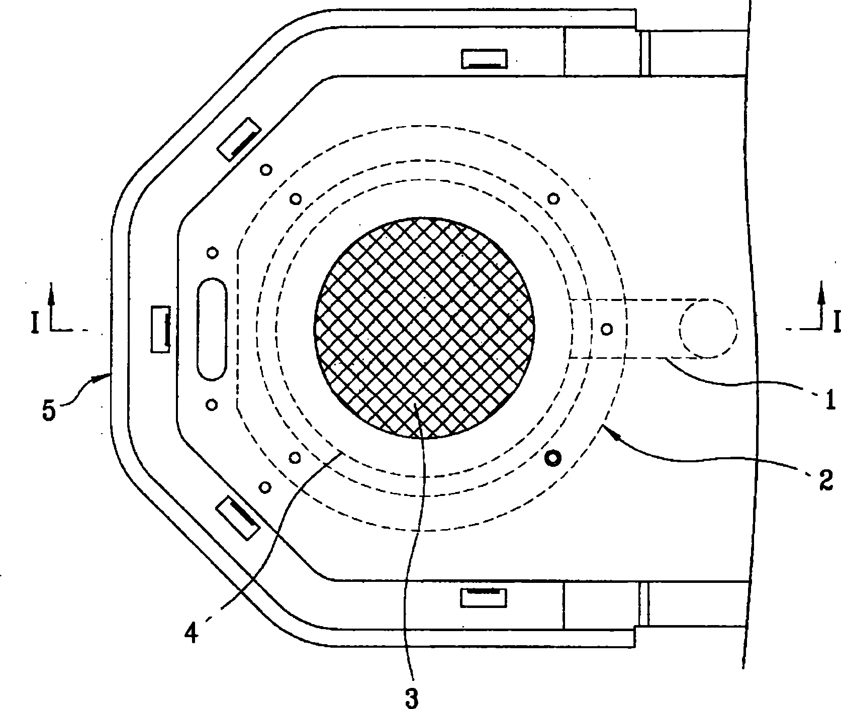
[0031] The gas furnace of the present invention will be described in detail below in conjunction with the accompanying drawings.

[0032] In order to avoid duplication of description, the same reference numerals are used for the same components as in the prior art.

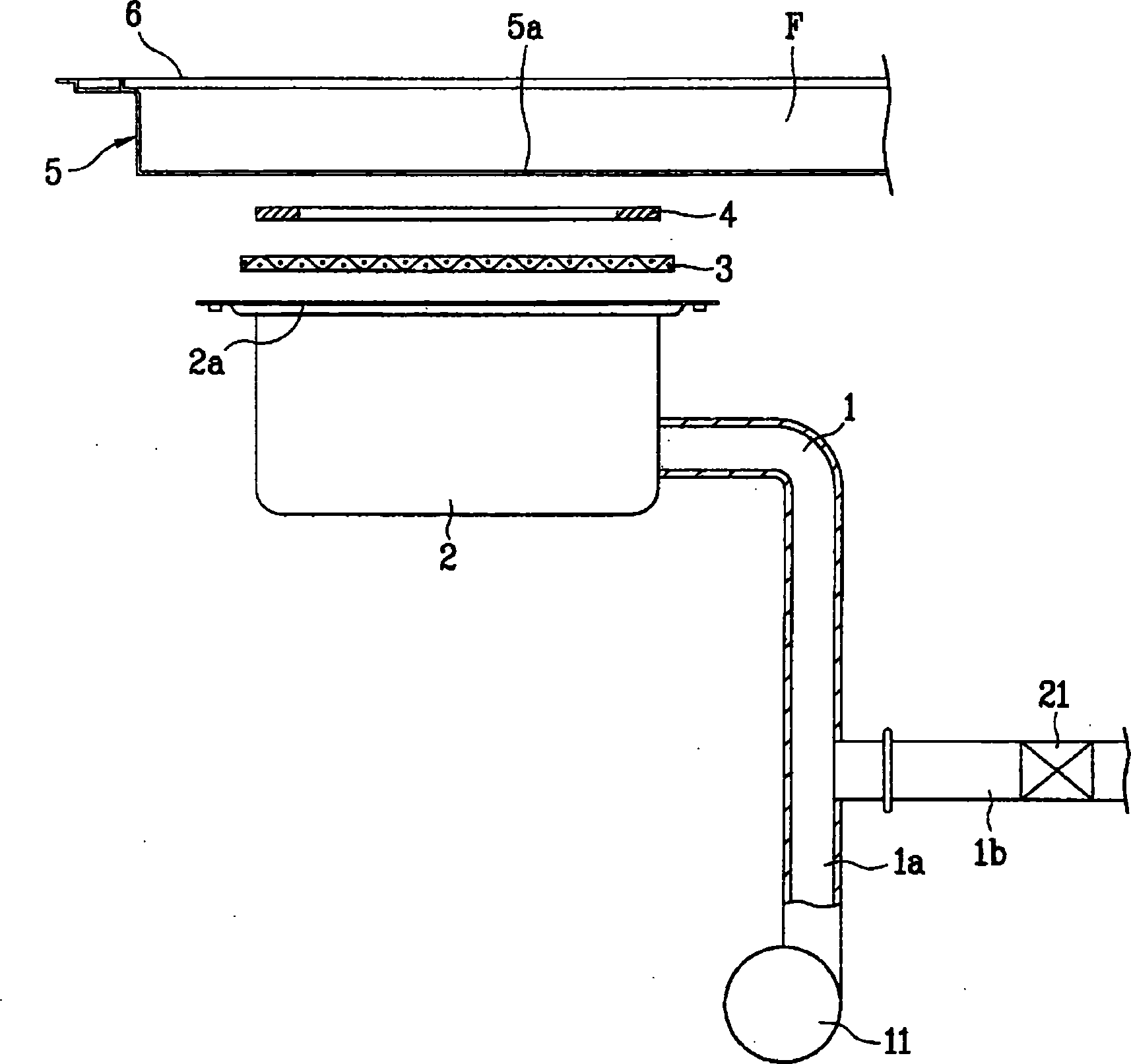
[0033] Such as Figure 4 As shown, in order to perceive the temperature of the glass dish (6), the gas furnace of the present invention is provided with a temperature sensor (100) on the lower surface of the glass dish (6), and is also provided with a temperature sensor connected to the temperature sensor and sensed according to the temperature sensor (100). The microcomputer (200) that controls the speed of the blower fan (11) according to the temperature of the glass plate (6).

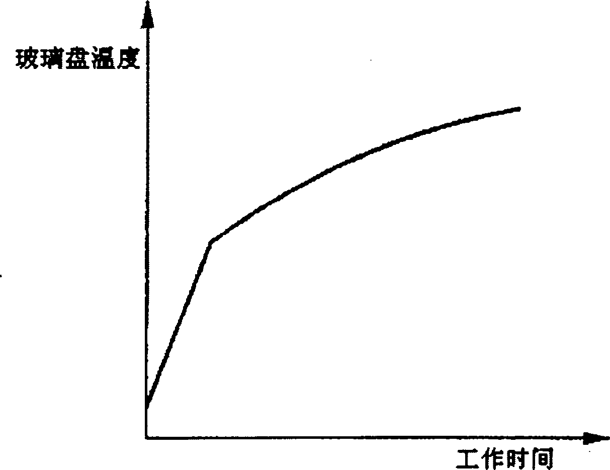
[0034] The temperature sensor (100) periodically measures the temperature of the glass plate (6), and when the temperature of the glass plate (6) rises above the reference value, the microcomputer (200) adjusts the speed of the blower fan


PUM


Abstract

The inventive gas stove comprises a stove door in which air-gas mixture is burning, a dog mounted in the upper part of the stove door, a stove frame firm-jointed with the fire door for fastening the stove edge, a glass disk mounted in the upper part of the frame for putting heated objects, a temperature sensor set on the lower surface of the glass disk for measuring the temperature of the glass disk and a microcomputer for controlling the rotation rate of the air supply fan according to the temperature sensed by the temperature sensor.

Description


Claims


Application Information

Patent Timeline
Owner LG ELECTRONICS (TIANJIN) APPLIANCES CO LTD
Why Eureka
Try Eureka