Manufacturing device
a manufacturing device and a technology for manipulators, applied in the direction of manipulators, metal-working devices, gripping heads, etc., can solve the problems of large size of the manufacturing device and high manufacturing cost, and achieve the effect of reducing size and manufacturing cos
- Summary
- Abstract
- Description
- Claims
- Application Information
AI Technical Summary
Benefits of technology
Problems solved by technology
Method used
Image

Examples
embodiment 1
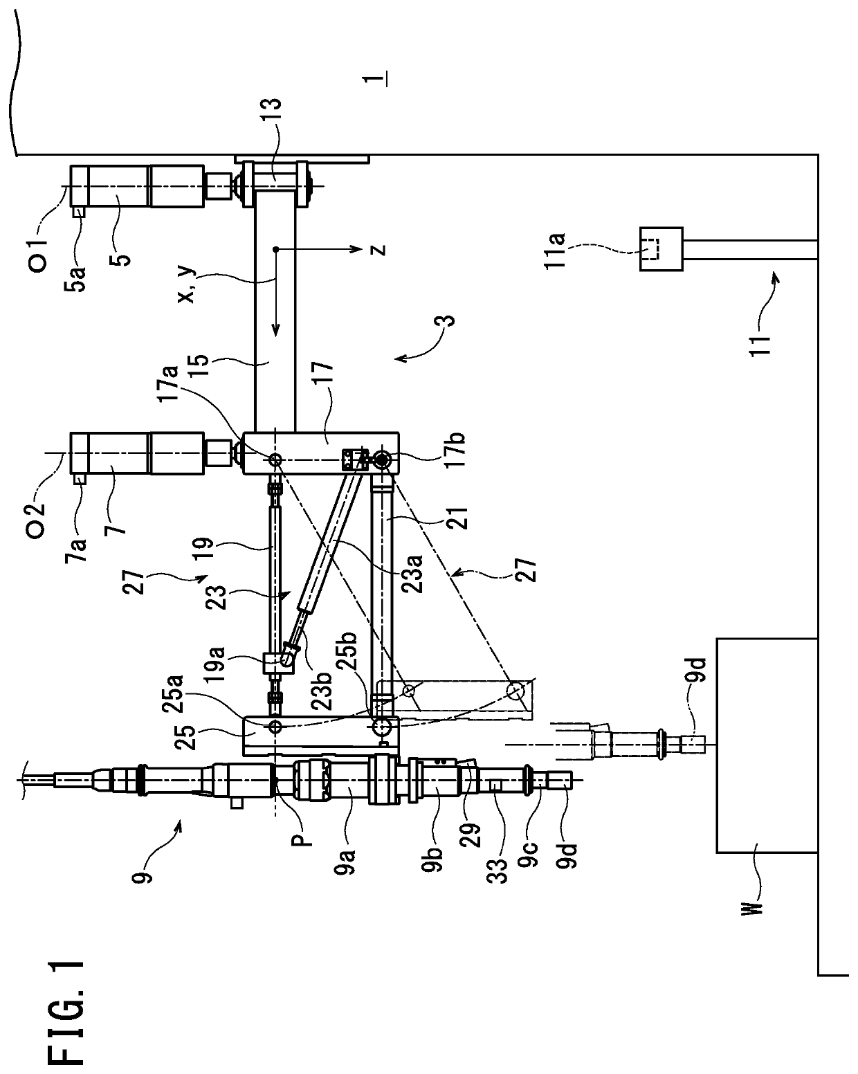
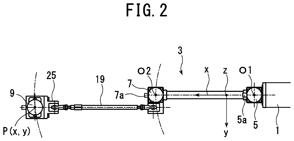
[0042]The manufacturing device of Embodiment 1 is a fastening device. As shown in FIGS. 1 and 2, this fastening device includes a base 1, a link mechanism 3, first and second servomotors 5, 7, and a known nut runner 9.
[0043]A workpiece W can be positioned and fixed on the base 1. In addition, a starting point confirmation stand 11 is provided on the base 1. A recess 11a, into which a socket 9d of the nut runner 9 is insertable from above, is formed in the upper end of the starting point confirmation stand 11.
[0044]The link mechanism 3 is provided on the base 1. In the link mechanism 3, a first hinge 13 is fixed to a side surface of the base 1. The first hinge 13 has a horizontal arm 15 that is swingable about vertically-extending, swing center axis O1. The horizontal arm 15 extends horizontally. A second hinge 17 is fixed to the tip end of the horizontal arm 15. The second hinge 17 has first and second links 19, 21 and a damper 23 that are swingable about vertically-extending, swing ce
embodiment 2
[0072]As shown in FIG. 10, the manufacturing device of Embodiment 2 is a pressure-applying device that uses a known servo press 10 as the manufacturing means.
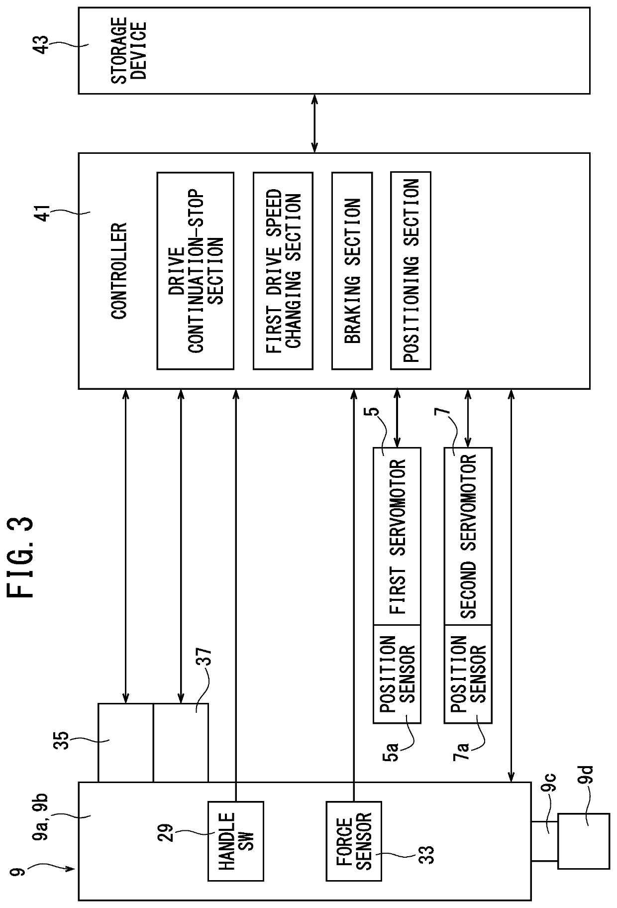
[0073]The servo press 10 encloses a servomotor, a speed reducer, and a rotating shaft that are not shown, and the rotating shaft is rotated by the servomotor. An acting part 10a is capable of pressing against workpiece by advancing straight ahead in the axial direction and by rotating the rotating shaft. The base 1, the link mechanism 3, the first and second servomotors 5, 7, the first and second position sensors 5a, 7a, the handle SW 29, the force sensor 33, the controller 41, and the storage device 43 are the same as the fastening device of Embodiment 1.
[0074]In this pressure-applying device, manufacturing work such as crimping and press-fitting of the workpiece can be performed by the servo press 10. Furthermore, in this pressure-applying device as well, a reduction of size can be realized and a reduction of manufacturing cost
embodiment 3
[0075]In the fastening device of Embodiment 3 as shown in FIG. 11, a current sensor 61 is additionally provided within the controller 41 in the fastening device of Embodiment 1. The current sensor 61 corresponds to operation state detection means. The current sensor 61 is capable of detecting the current value of the current being supplied to the first and second servomotors 5, 7. In addition, a program capable of executing the flowcharts shown in FIGS. 12, 6, and 7 is stored in the controller 41. Other constituents of Embodiment 3 are the same as Embodiment 1. Hence, constituents that are the same as Embodiment 1 are assigned the same reference symbols, and descriptions thereof are simplified or omitted.
[0076]By turning on an operation switch, this fastening device operates according to the flowchart of FIG. 12. First, initialization is performed in step S31 in the same manner as in step S1 shown in FIG. 5 of Embodiment 1.
[0077]Then, in step S32, each of the target coordinates is stor
PUM
| Property | Measurement | Unit |
|---|---|---|
| Pressure | aaaaa | aaaaa |
| Speed | aaaaa | aaaaa |
| Current | aaaaa | aaaaa |
Abstract
Description
Claims
Application Information
 - R&D Engineer
- R&D Manager
- IP Professional
- Industry Leading Data Capabilities
- Powerful AI technology
- Patent DNA Extraction
Browse by: Latest US Patents, China's latest patents, Technical Efficacy Thesaurus, Application Domain, Technology Topic.
© 2024 PatSnap. All rights reserved.Legal|Privacy policy|Modern Slavery Act Transparency Statement|Sitemap