Electronic device fastener

Active Publication Date: 2021-09-28
SK HYNIX INC
View PDF35 Cites 1 Cited by
  • Summary
  • Abstract
  • Description
  • Claims
  • Application Information

AI Technical Summary

Benefits of technology

[0007]In yet another embodiment, an electronic device fastening system includes a glider component having first and second glider base, each glider base having a first surface with a gliding guide and a guide wall formed thereon extending in parallel on the first surface, whereby an edge of the first surface of each glider base extending from the guide wall forms a shelf for the electronic device to rest on. The glider component further includes a handle bar coupling an end of the first glider base to an end of the second glider base forming a monolithic structure for the glider component. The fastening system further includes first and second slider tracks, each slider track having a first foot and a second foot with a track gap formed therebetween, each foo

Problems solved by technology

The process of securing an electronic device onto a board may damage the device.
Components on the M.2 SSD are therefore fully exposed and as a result can be easily knocked loose or damaged by external forces introduced during handling and installation.
Moreover, the device PCB itself can be damaged as a result of bending when the device is inserted into, or removed from, the host without proper h

Method used


Image

  • Electronic device fastener
  • Electronic device fastener
  • Electronic device fastener

Examples


Embodiment Construction

[0020]A detailed description of various exemplary embodiments of the present disclosure is provided below along with accompanying figures that illustrate aspects of the exemplary embodiments. It is to be understood that specific details set forth below are exemplary and are for purposes of providing a better understanding of the invention as well as to provide those skilled in this art with an enabling description for implementing various embodiments. The scope of the invention is not limited to the specific and exemplary embodiments described herein.

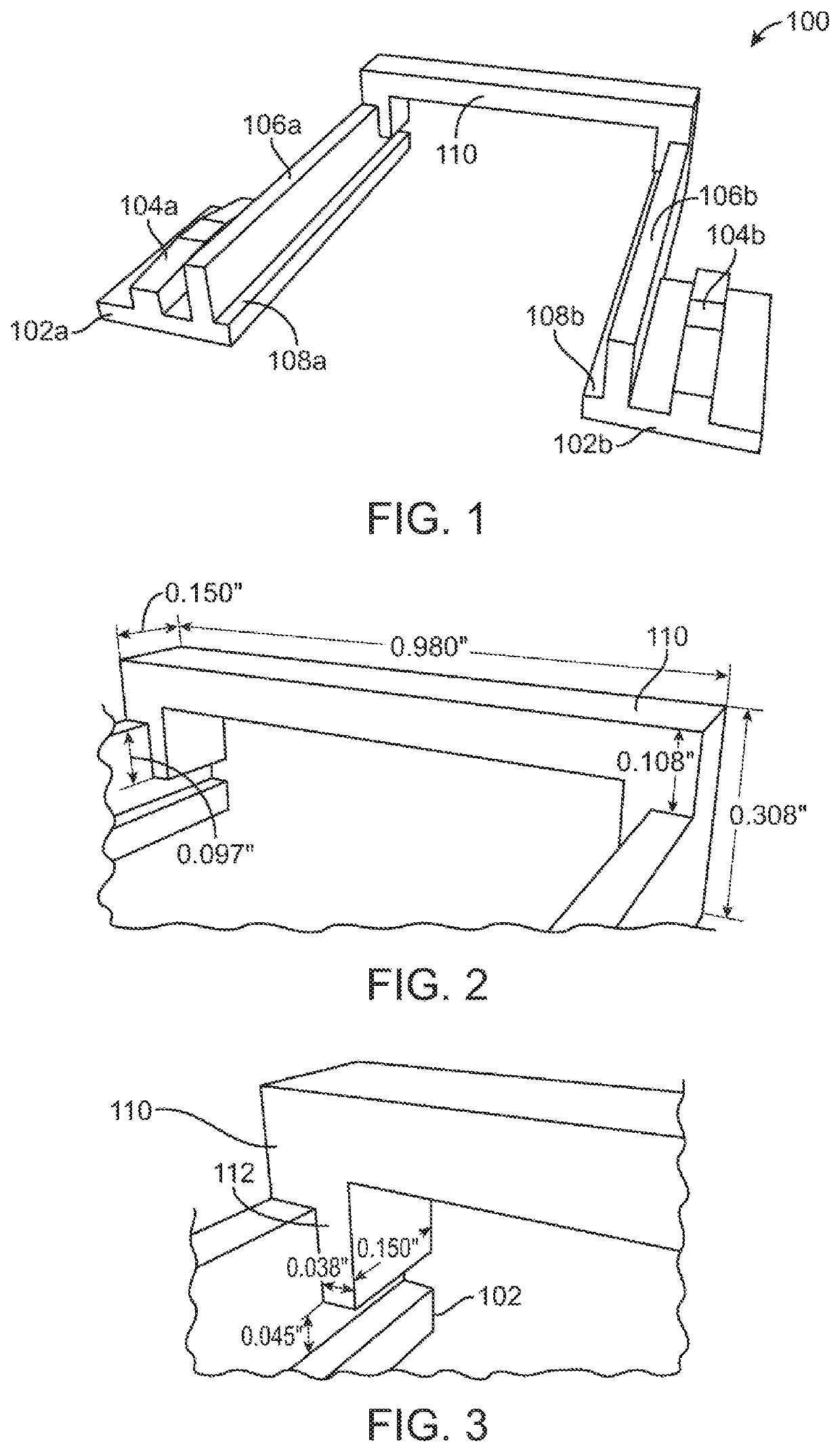
[0021]Referring to FIG. 1, there is shown an isometric view of an exemplary glider component 100 of an electronic device fastening system according to one exemplary embodiment of the present disclosure. Glider component 100 includes first and second gliding bases 102. Gliding bases 102 allow glider component 100 to sit flat on the surface of a host board such as a printed circuit board PCB (not shown). On a top surface of each gliding base


PUM


Abstract

Embodiments for electronic device fasteners that enable an electronic device to be reliably and quickly secured on a host board are presented. In one exemplary embodiment, a fastening assembly includes a glider component that supports an electronic device such as an M.2 solid state drive, and slides on tracks installed on a host board to bring a handle bar in a locking position above the electronic device securing the electronic device in place. The glider component and the tracks are designed with sloped surfaces such that as the glider component slides over the tracks, when it reaches an end of the track, a stable engagement secures the electronic device in place without the need for any additional fastening mechanisms.

Description


Claims


Application Information

Patent Timeline
Owner SK HYNIX INC
Why Eureka
Try Eureka