Displacement measurement device and displacement measurement method
a technology of displacement measurement and displacement measurement, which is applied in the direction of bridges, instruments, image enhancement, etc., can solve the problem of captured image may have shot noise, and achieve the effect of higher level of accuracy
- Summary
- Abstract
- Description
- Claims
- Application Information
AI Technical Summary
Benefits of technology
Problems solved by technology
Method used
Image

Examples
embodiment 1
1-1. Overview of Displacement Measurement System
[0058]A displacement measurement system that captures a plurality of images of a subject to be measured and calculates a displacement of the subject from the plurality of captured images, and a displacement measurement device included in the displacement measurement system, will be described here.
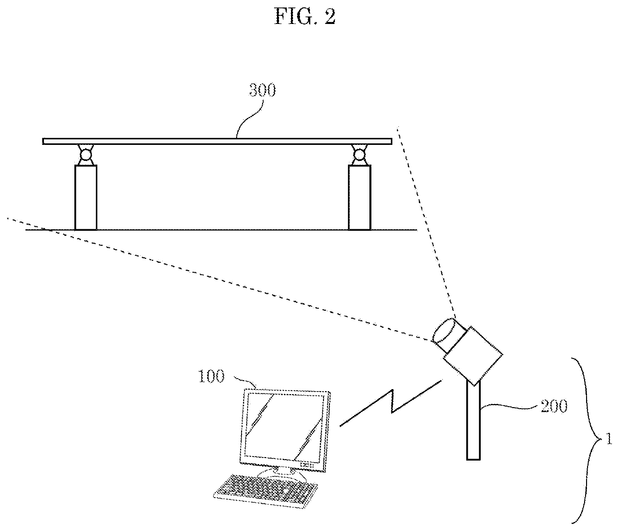
[0059]FIG. 2 is an exterior view illustrating an example of the configuration of displacement measurement system 1 according to Embodiment 1.
[0060]As illustrated in FIG. 2, displacement measurement system 1 is configured including image capturing device 200 and displacement measurement device 100.
[0061]Image capturing device 200 captures an image of subject 300, which is a subject to be measured. Image capturing device 200 captures, for example, a plurality of images of subject 300 over time, from a fixed angle of view.
[0062]For example, when displacement measurement device 100 is to train first machine learning model 10 (described later), image
embodiment 2
[0120]A displacement measurement device according to Embodiment 2, configured by changing part of the configuration of displacement measurement device 100 according to Embodiment 1, will be described next.
[0121]The displacement measurement device according to Embodiment 2 will be described hereinafter, focusing on differences from displacement measurement device 100 according to Embodiment 1.
2-1. Configuration of Displacement Measurement Device 400
[0122]FIG. 10 is a block diagram illustrating the configuration of displacement measurement device 400 according to Embodiment 2.
[0123]As illustrated in FIG. 10, displacement measurement device 400 is configured by changing displacement measurement device 100 according to Embodiment 1 as follows: first machine learning model 10 has been changed to first machine learning model 410; second obtainer 60 has been changed to second obtainer 460; and first trainer 70 has been changed to first trainer 470.
[0124]First machine learning model 410 is a m
embodiment 3
[0153]A displacement measurement device according to Embodiment 3, configured by changing part of the configuration of displacement measurement device 400 according to Embodiment 2, will be described next.
[0154]The displacement measurement device according to Embodiment 3 will be described hereinafter, focusing on differences from displacement measurement device 400 according to Embodiment 2.
3-1. Configuration of Displacement Measurement Device 500
[0155]FIG. 14 is a block diagram illustrating the configuration of displacement measurement device 500 according to Embodiment 3.
[0156]As illustrated in FIG. 14, displacement measurement device 500 is configured by changing displacement measurement device 400 according to Embodiment 2 as follows: first machine learning model 410 has been changed to first machine learning model 510; first generator 30 has been changed to first generator 530; hypothetical displacement calculator 40 has been changed to hypothetical displacement calculator 540; a
PUM
 Abstract
Description
Claims
Application Information
 - R&D Engineer
- R&D Manager
- IP Professional
- Industry Leading Data Capabilities
- Powerful AI technology
- Patent DNA Extraction
Browse by: Latest US Patents, China's latest patents, Technical Efficacy Thesaurus, Application Domain, Technology Topic.
© 2024 PatSnap. All rights reserved.Legal|Privacy policy|Modern Slavery Act Transparency Statement|Sitemap