Data form having a position-coding pattern detectable by an optical sensor
a technology of position-coding pattern and data form, which is applied in the field of data form having a position-coding pattern detectable by an optical sensor, can solve the problems of difficult identification and deciphering of form entries, difficult automatic form recording, and complex image analysis software, etc., and achieve good resolution
Inactive Publication Date: 2002-05-02
ANOTO AB
View PDF19 Cites 80 Cited by
- Summary
- Abstract
- Description
- Claims
- Application Information
AI Technical Summary
Benefits of technology
In this patented technology, it describes how certain types of codes have been identified by printing them onto paper or other materials. These codes can then be detected through sensors placed at specific locations within these materials. By analyzing the code patterns, the system can help predict what parts of the material they will receive during production.
Problems solved by technology
The technical problem addressed in this patent text is how to improve the efficiency and accuracy of data processing by reducing errors or improving the quality of the processed data.
Method used
View moreImage
Smart ImageViewing Examples

Examples
Embodiment Construction
, with each claim standing on its pwn as a separate preferred embodiment of the invention.
Login to view more PUM
 Abstract
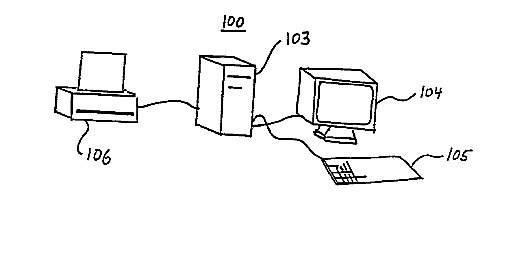
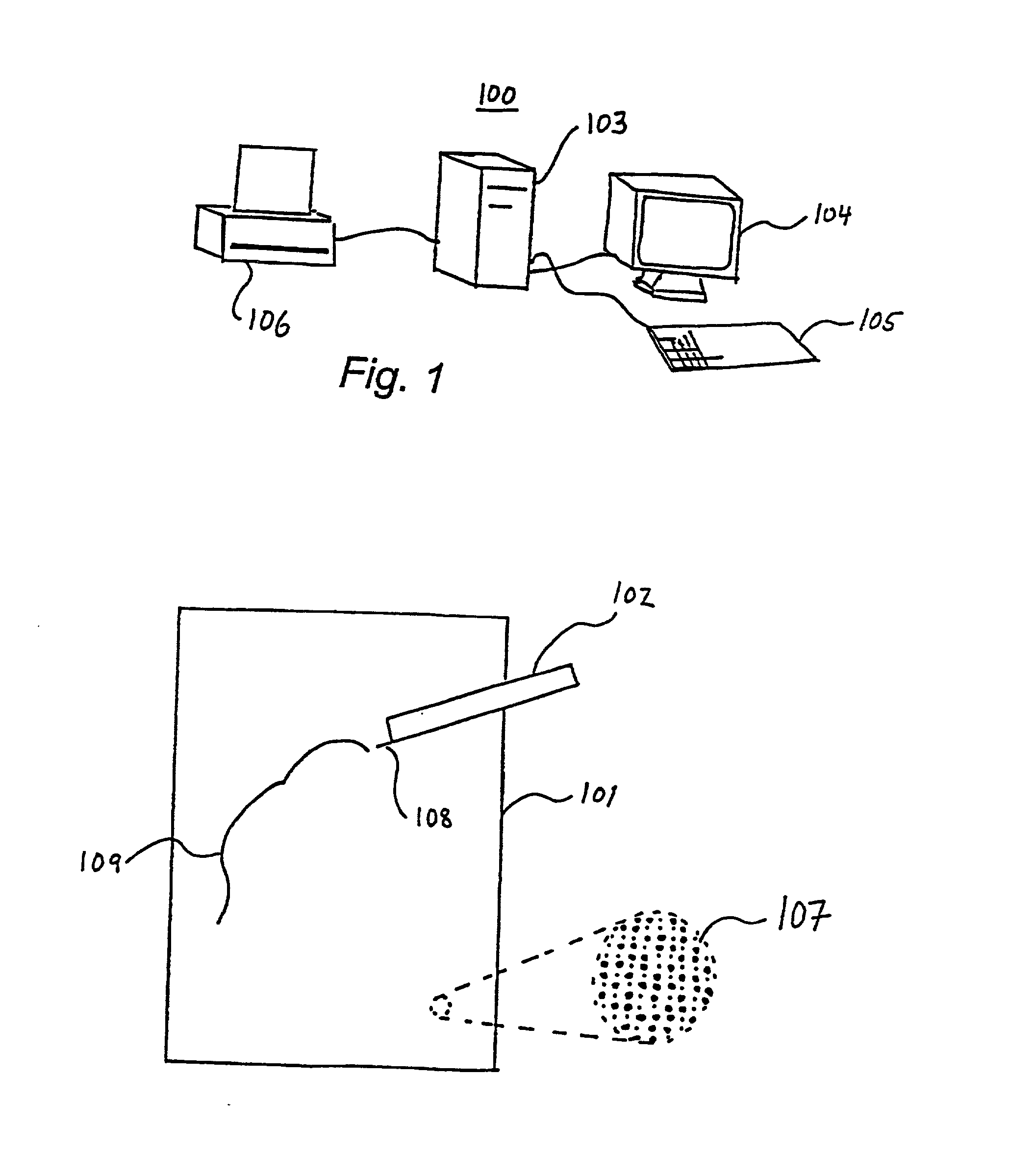
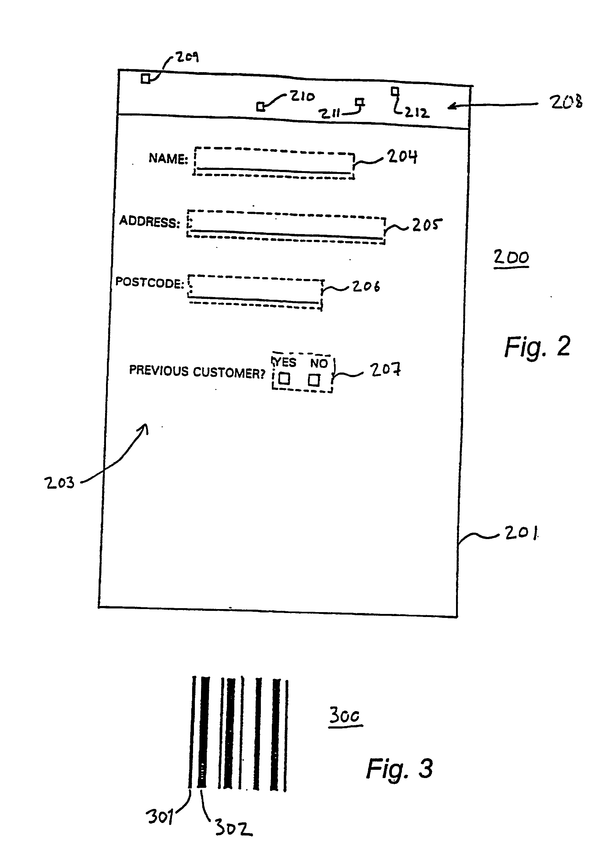
Disclosed is a form having a form layout with at least one entry field. It may be printed on a base in the form of a sheet (or any other surface). The surface of the base may have a position-coding pattern. The entry field can be completed using a user unit that has an optical sensor to detect positions on the sheet utilizing the position-coding pattern. The optical sensor can thereby enable digital recording of the information entered in the entry field. The surface may also have an identity pattern that can identify the form layout after recordation by the sensor of the locations defined by the identity pattern.
Description
Login to view more Claims
Login to view more Application Information
Patent Timeline
 Owner ANOTO AB
- R&D Engineer
- R&D Manager
- IP Professional
Why Eureka
- Industry Leading Data Capabilities
- Powerful AI technology
- Patent DNA Extraction
Try Eureka
Browse by: Latest US Patents, China's latest patents, Technical Efficacy Thesaurus, Application Domain, Technology Topic.
© 2024 PatSnap. All rights reserved.Legal|Privacy policy|Modern Slavery Act Transparency Statement|Sitemap