Apparatus and buffing element for reconditioning digital recording discs

a technology buffing elements, applied in the field of reconditioning the protective surface of digital recording discs, can solve the problems of many used discs not being resold, affecting playback quality and visual appearance, and interfering with the laser beam before it reaches the data layer, etc., to achieve the effect of restoring both playback quality and visual appearance, and effectively reconditioning the protective surface of the dis

Inactive Publication Date: 2002-11-14
BAUER JASON
View PDF0 Cites 4 Cited by
  • Summary
  • Abstract
  • Description
  • Claims
  • Application Information

AI Technical Summary

Benefits of technology

This patented device relieves badges or defects caused during manufacturing processes used to repair damaged CD's (Compact Disc). It uses two different types of cleaners: hard disk cleaner(HDD) which removes any debris left over after use; and soft roller elements that remove excess materials while maintaining good vision when viewed against normal background images. These technical improvements improve image sharpness and reduce wear patterns on the CD itself.

Problems solved by technology

The technical problem addressed in this patented text relates to improving the durability and usability of digital storage media discs while maintaining their functionality over time. Existing solutions involve adding layers made of materials called dull marks which cause wear out and reduce image clarity after repeated uses. Other existing solution require expensive tools and processes to recover lost playing power.

Method used


Image

  • Apparatus and buffing element for reconditioning digital recording discs
  • Apparatus and buffing element for reconditioning digital recording discs
  • Apparatus and buffing element for reconditioning digital recording discs

Examples


Embodiment Construction

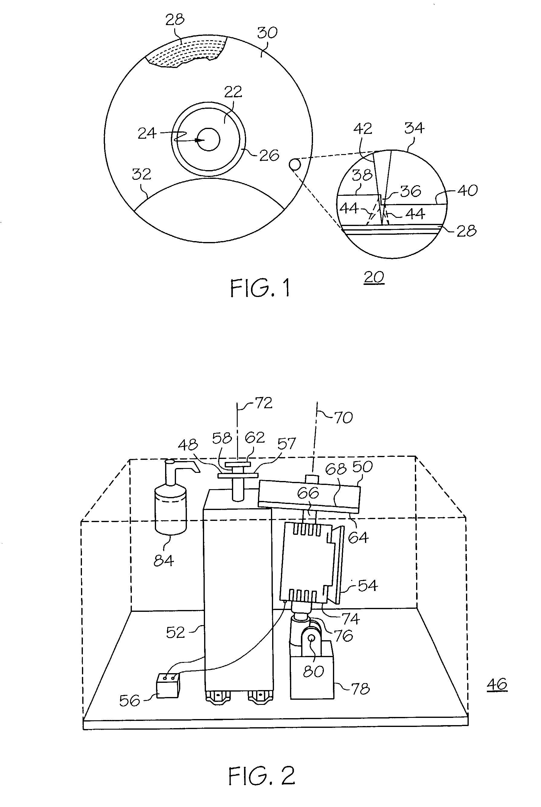
[0025] FIG. 1 shows a diagram of an optically-read digital recording disc 20. optically-read digital recording disc 20 generally includes a center section, or clamping area 22, located about a center hole 24 of disc 20. Surrounding clamping area 22 is a narrow text band 26 typically used to identify the manufacturer. Clamping area 22 and text band 26 to not contain encoded data. A data layer 28 lies outside of text band 26. Data layer 28 is arranged in spiral tracks and is covered by a protective surface 30. Disc 20 is shown with a portion of protective surface 30 removed to show the underlying spiral arranged data layer 28. An abrasion pattern 32 created in accordance with a disc reconditioning apparatus is shown on protective surface 30 and will be described in detail below.

[0026] When disc 20 is a music compact disc (CD), the first band of data layer 28 closest to text band 26, called the "lead-in", contains the table of contents for the CD. The lead-in tells the CD playback equipme


PUM


Abstract

An apparatus (46) for reconditioning a protective surface (30) of an optically-read digital recording disc (20) includes a turntable (48) configured to receive a center hole (24) of the disc (20) and a first motor (52), coupled to the turntable (48), for rotating the turntable (48) and the disc (20) at a first rotational speed. The apparatus further includes a buffing element (50) for removing an amount of material from the protective surface (30) as the turntable rotates the disc (20) and a second motor (54), coupled to the buffing element (50) for rotating the buffing element (50) at a second rotational speed. A timing element (56) synchronizes the first and second motors (52, 54) to substantially simultaneously cease rotation of the turntable (48) and the buffing element (50) following removal of an amount of material from the disc (20). The buffing element (50) includes a substantially rigid stabilizer plate (92) and a foam pad (88, 90) fixedly engaged with a plate surface (96) of the stabilizer plate (92). A buffing pad (82) is in fixed relation with the foam pad (88, 90). The buffing pad has a first surface (102) configured to face the foam pad (88, 90) and a second surface (104) configured to recondition the protective surface (30) of the disc (20).

Description


Claims


Application Information

Patent Timeline
Owner BAUER JASON
Why Eureka
Try Eureka