Persistent current switch and method for the same

a current switch and persistent technology, applied in the direction of permanent superconductor devices, superconducting magnets/coils, magnetic bodies, etc., can solve the problems of long time to drive a pcs, large number of switching times, long operating time for switching, etc., to improve the performance of superconducting magnetic energy storage, short operation time, and large capacity without energy loss

Inactive Publication Date: 2002-12-19
RAILWAY TECH RES INST
View PDF1 Cites 13 Cited by
  • Summary
  • Abstract
  • Description
  • Claims
  • Application Information

AI Technical Summary

Benefits of technology

The present invention provides a way to efficiently store high-capacity electrical energy by supplying very small amounts of electricity through a strong magnetic material. This results in less energy being lost during turning on or off. Additionally, there are ways to make this switch work quickly while still maintaining its effectiveness.

Problems solved by technology

The technical problem addressed in this patent text relates to the challenge of achieving both sufficient mechanical strength and durability in a superconducting magnetic energy storage system. Current methods involve using expensive materials and complex processes, leading to reduced efficiency and increased costs associated with the production of the superconducting inductor.

Method used


Image

  • Persistent current switch and method for the same
  • Persistent current switch and method for the same
  • Persistent current switch and method for the same

Examples


Embodiment Construction

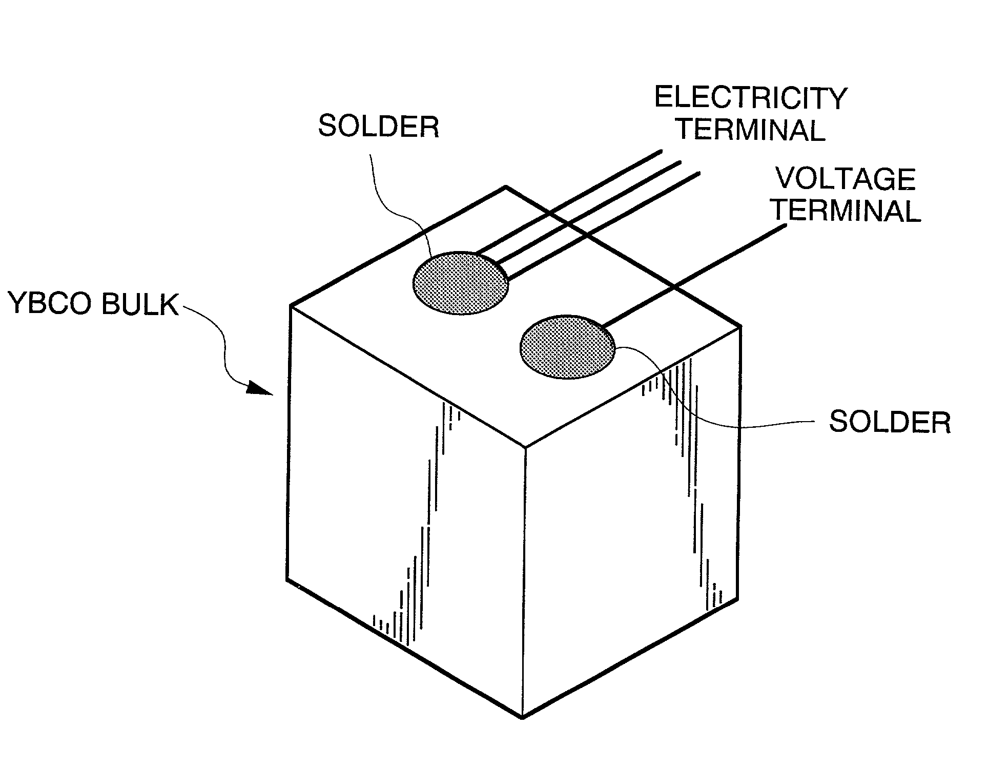
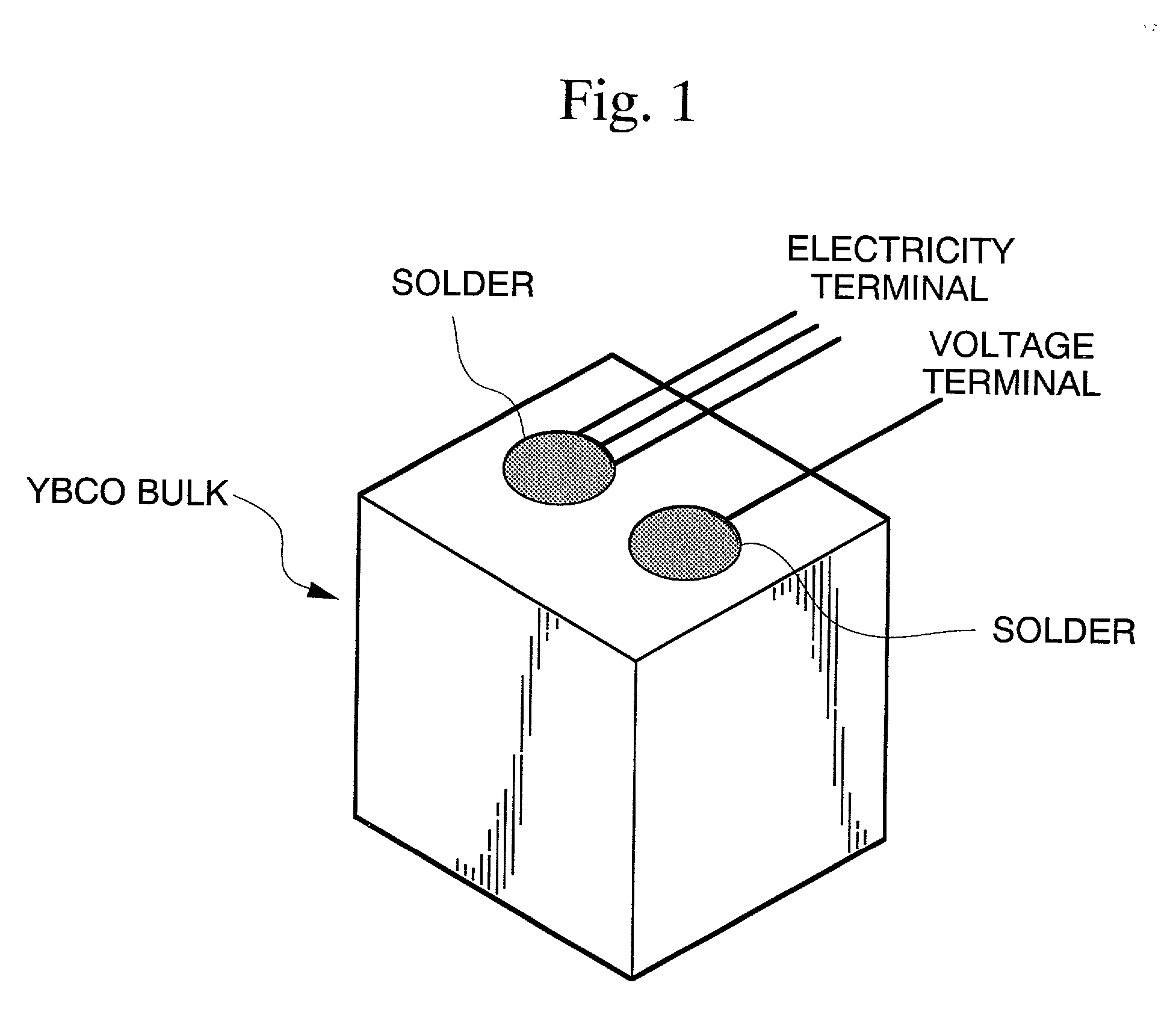
[0036] In the present invention, a bulk RE-Ba--Cu--O superconductor (RE is a rare earth such as Y, La, Nd, Sm, Eu, Gd, Dy, Ho, Er, Tm, Yb) is a copper oxide superconductor of which the main phase is REBa.sub.2Cu.sub.3Oy with RE.sub.2BaCuO.sub.5 as a secondary phase. A bulk RE-Ba--Cu--O superconductor may include Ag for the purpose of increasing the mechanical strength. Furthermore, the bulk superconductor is manufactured by a melt process. Required performance as a connector material for a mechanical persistent current switch cannot be obtained with RE-Ba--Cu--O superconductors manufactured by a sintering method.

[0037] For a method of impregnating resin into a bulk RE-Ba--Cu--O superconductor made by a melt process, the technique according to Japanese Patent (Granted) Publication No. 3144675 in that the resin is impregnated into a bulk superconductor by immersing it in molten resin under reduced pressure can be applied.

[0038] For a resin which is impregnated into a bulk superconductor,


PUM


Abstract

In order to provide an inexpensive mechanical persistent current switch with a short operation time and a large capacity without causing energy loss, a mechanical persistent current switch comprises a bulk member which is made of RE-Ba-Cu-O superconductor (RE is a rare earth element), connector material, and the bulk member made of RE-Ba-Cu-O superconductor is made by a melt process in which resin is impregnated, and an current terminal and a voltage terminal pasted onto the bulk member.

Description


Claims


Application Information

Patent Timeline
Owner RAILWAY TECH RES INST
Why Eureka
Try Eureka