Image processing device, image processing method, image processing program and recording medium

Inactive Publication Date: 2004-06-17
SONY CORP
View PDF5 Cites 21 Cited by
  • Summary
  • Abstract
  • Description
  • Claims
  • Application Information

AI Technical Summary

Benefits of technology

0028] FIG. 8A, FIG. 8B, and FIG. 8C are schematic diagrams more p

Problems solved by technology

In contrast, in a complicated picture region, when the compressing process is performed, the deterioration of the picture quality is not remarkable.
This method is effective when the compression rate is high and the code amount is not affordable.
Howev

Method used


Image

  • Image processing device, image processing method, image processing program and recording medium
  • Image processing device, image processing method, image processing program and recording medium
  • Image processing device, image processing method, image processing program and recording medium

Examples


Embodiment Construction

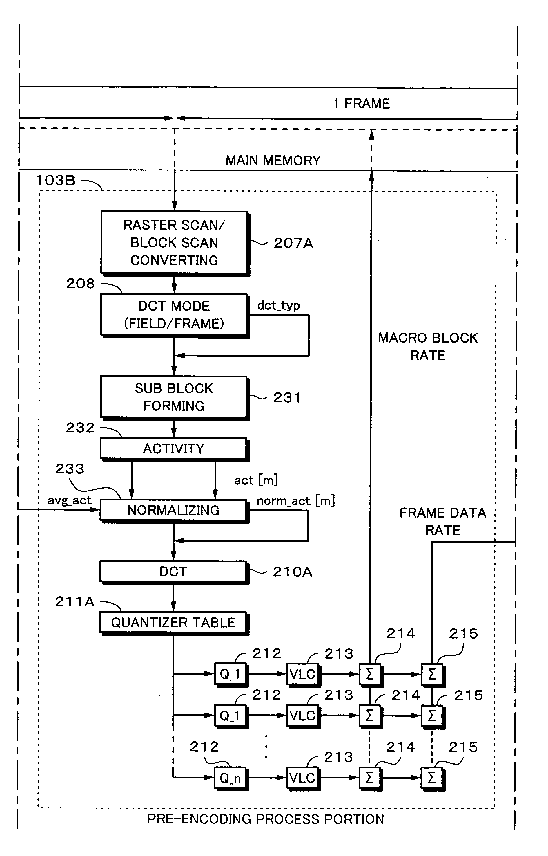
[0040] Next, an embodiment of the present invention will be described. According to the present invention, the DCT (Discrete Cosine Transform) is performed in the unit of one block of eight pixels.times.eight lines, of which one macro block of 16 pixels.times.16 lines as an encoding unit is divided by four. When the obtained DCT coefficients are quantized corresponding to a quantizer scale, the macro block is divided into sub blocks each of which is composed of for example four pixels.times.four lines. An activity of each sub block is detected. Corresponding to the detected activities, an activity of each macro block is determined. Corresponding to the activity, a quantizer scale of each macro block is determined. With the determined quantizer scales, macro blocks are adaptively quantized.

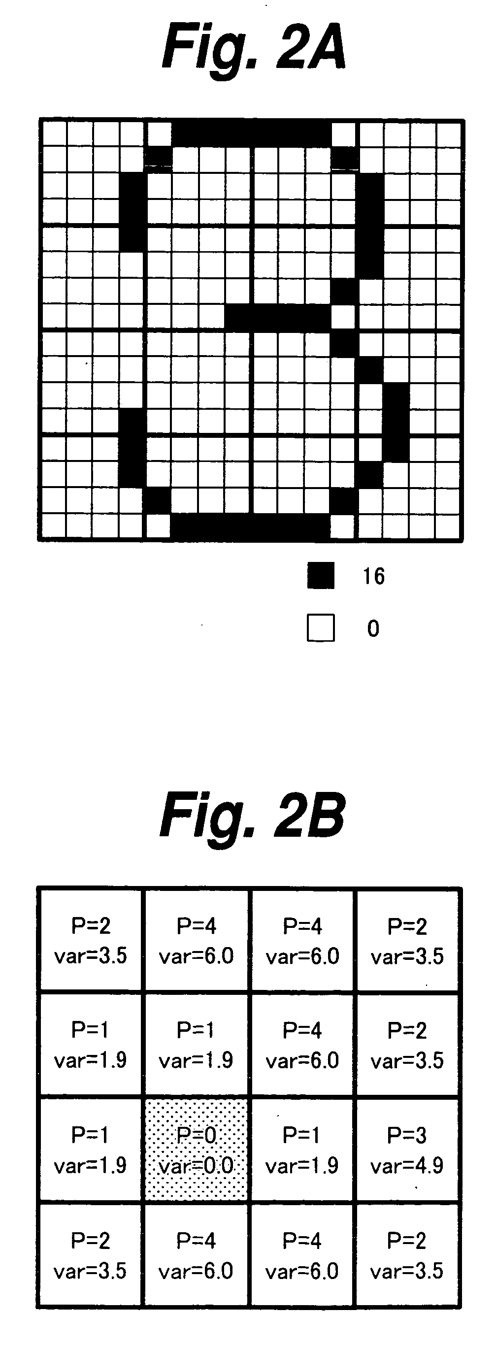
[0041] With reference to FIG. 2A, FIG. 2B, FIG. 3A, and FIG. 3B, the activity detecting method according to the present invention will be described in comparison with that of the MPEG2 TM5 as the rela


PUM


Abstract

Occurrence of mosquito noise of a macro block that contains even a small plain region is suppressed. One macro block is subdivided into sub blocks each of which is composed of four pixelsxfour lines. The average value of luminance levels of each sub block is calculated. The absolute values of the difference values between the luminance levels and the average value are obtained for each sub block. The minimum value of the average difference values of the 16 sub blocks of one macro block is selected and decided as an activity of the macro block. Corresponding to the decided activity, a quantizer scale of the macro block is decided. With the decided quantizer scale, the macro block is quantized. According to this method, since the size of each sub block is smaller than the size of a conventional sub block of eight pixelsxeight lines, the average difference value of each sub block is more emphasized. Since the minimum value of the average difference values is designated as an activity of the macro block, an activity of a macro block that contains even a small plain portion can be more suppressed. As a result, a quantizer value of a macro block that contains an edge can be decreased. Thus, mosquito noise of a macro block that contains an edge portion of a picture can be suppressed.

Description


Claims


Application Information

Patent Timeline
Owner SONY CORP
Why Eureka
Try Eureka