Image heating apparatus

Active Publication Date: 2005-01-13
CANON KK
View PDF6 Cites 33 Cited by
  • Summary
  • Abstract
  • Description
  • Claims
  • Application Information

AI Technical Summary

Benefits of technology

[0018] It is an object of the present invention to provide an image heating apparatus that can suppress a failure in heating of an image.
[0019] It is another object of the present invention to provide an image heating apparatus that can suppress a failure in heating of an image even if a contact position of a thermoprotector with a heater more or less deviates in a recording-material moving direction.
[0020] According to one aspect of the present invention, an image heating apparatus includes a heater for heating an image formed on a recording material, and a thermoprotector for suppressing an excessive temperature rise of the heater. The thermoprotector includes a heat collecting portion contacting the heater. A width of the heat collecting portion in a moving direction of the recording material is larger than a width of the heater in the moving direction of the recording material.

Problems solved by technology

As a result, sufficient heat quantity is not supplied to the recording material as compared to positions of the heater other than the contact position of the heater with the thermoprotetor, sometimes resulting in a failure in fixing at the contact position.
It has become clear that if the contact position of the safety element with the heater deviates from a designed position in a direction of ends of the heater (the sheet feeding direction), a high-temperature offset of a toner image and a failure in an image, such as unevenness in gloss, or the like, occur.
It has become clear that the temperature distribution in a contact portion of the heater with the safety element differs from the temperature distribution in other portions of the heater in the longitudinal direction, and a high-temperature offset, a failure in fixing, and unevenness in gloss occur at the contact portion of the heater with the safety element.

Method used


Image

  • Image heating apparatus
  • Image heating apparatus
  • Image heating apparatus

Examples


Example

[0031] (First Embodiment)

[0032] (1) Example of an Image Forming Apparatus

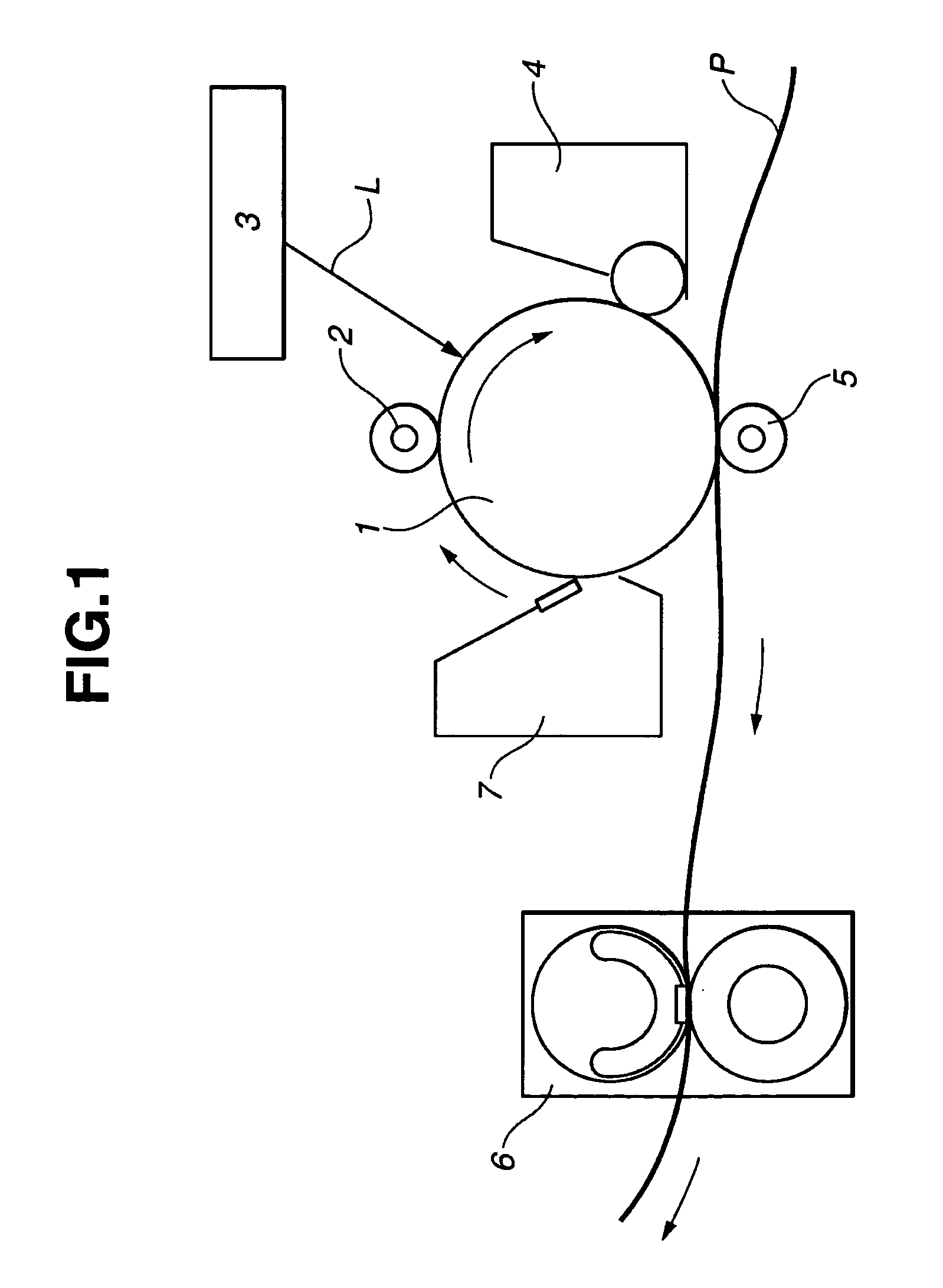
[0033]FIG. 1 is a schematic diagram illustrating the configuration of an image forming apparatus according to a first embodiment of the present invention. This image forming apparatus is a laser printer using a transfer-type electrophotographic process having a process speed of 127 mm / s and a throughput of 22 ppm (LTR).

[0034] A photosensitive drum 1 serves as an image bearing member, and is obtained by forming a layer of a photosensitive material, such as an OPC (organic photoconductor), amorphous Se, amorphous Si, or the like, on a cylindrical substrate made of aluminum, nickel, or the like.

[0035] The photosensitive drum 1 is rotatably driven in the direction of an arrow at a predetermined circumferential speed. First, the surface of the photosensitive drum 1 is uniformly charged to a predetermined polarity and a predetermined potential by a charging roller 2, serving as a charging apparatus.

[0036] Then, t

Example

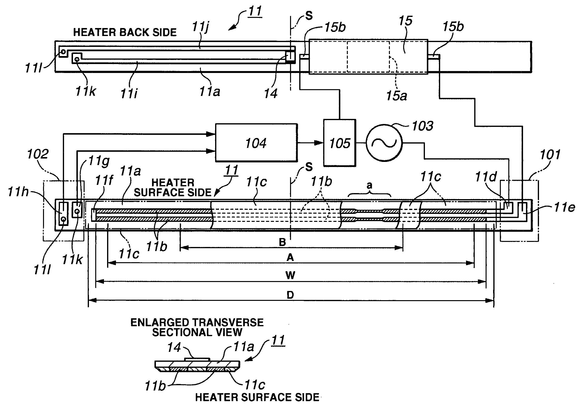
[0103] (Second Embodiment)

[0104] In a second embodiment of the present invention, a configuration will be described in which, as shown in FIG. 8, a grease obtained by dispersing a heat conductive filler is used as the heat conductive filler 16 provided at the contact surface between the heat collecting plate 15a of the thermoprotector 15 and the heater 11 for improving the response property of the thermoprotector 15 and stabilization, and a heat-conductive-grease extrusion preventing member (grease extrusion regulating member) for preventing (suppressing) extrusion of the heat-conductive grease 16 to the surface side, i.e., a sliding surface with the fixing film, of the heater 11. Since other conditions are the same as in the first embodiment, further description thereof will be omitted.

[0105] As in the first embodiment, when the size F of the heat collecting plate 15a of the thermoprotector 15 is made larger than the width E of the heater 11, the heat-conductive grease 16 provided a


PUM


Abstract

The present invention relates to an image heating apparatus, such as a heating fixing apparatus for fixing a toner image formed on plane paper. By making the width of a heat collecting plate of a thermoprotector for suppressing an excessive temperature rise of a heater provided in the apparatus, a failure in an image is suppressed irrespective of variations in the mounting position of the thermoprotector.

Description


Claims


Application Information

Patent Timeline
Owner CANON KK
Why Eureka
Try Eureka