Nebulizer with plasma source

Inactive Publication Date: 2005-08-11
METARA
View PDF13 Cites 15 Cited by
  • Summary
  • Abstract
  • Description
  • Claims
  • Application Information

AI Technical Summary

Benefits of technology

[0014] One aspect of the present invention provides the integration of a plasma ionization source and an electrospray ionization capability in a mass spectrometer such that the different ionization sources can be operated independently or together to achieve sample ionization in the way that is optimal for the analytical need at hand. One embodiment makes use of a microwave-i

Problems solved by technology

However, the energetics present in the electrospray ionization source are not sufficient to break all components of the molecular species that may be present into their elemental components even in the hard ionization mode.
The elemental sensitivity when using this type of source is limited by the fact that elemental species are distributed in a number of molecular fragments even after ionization.
This degradation significantly reduces the sensitivity for trace contamination and other constituents that are important for successful measurement of the analyte.
Since this technique

Method used


Image

  • Nebulizer with plasma source
  • Nebulizer with plasma source
  • Nebulizer with plasma source

Examples


Embodiment Construction

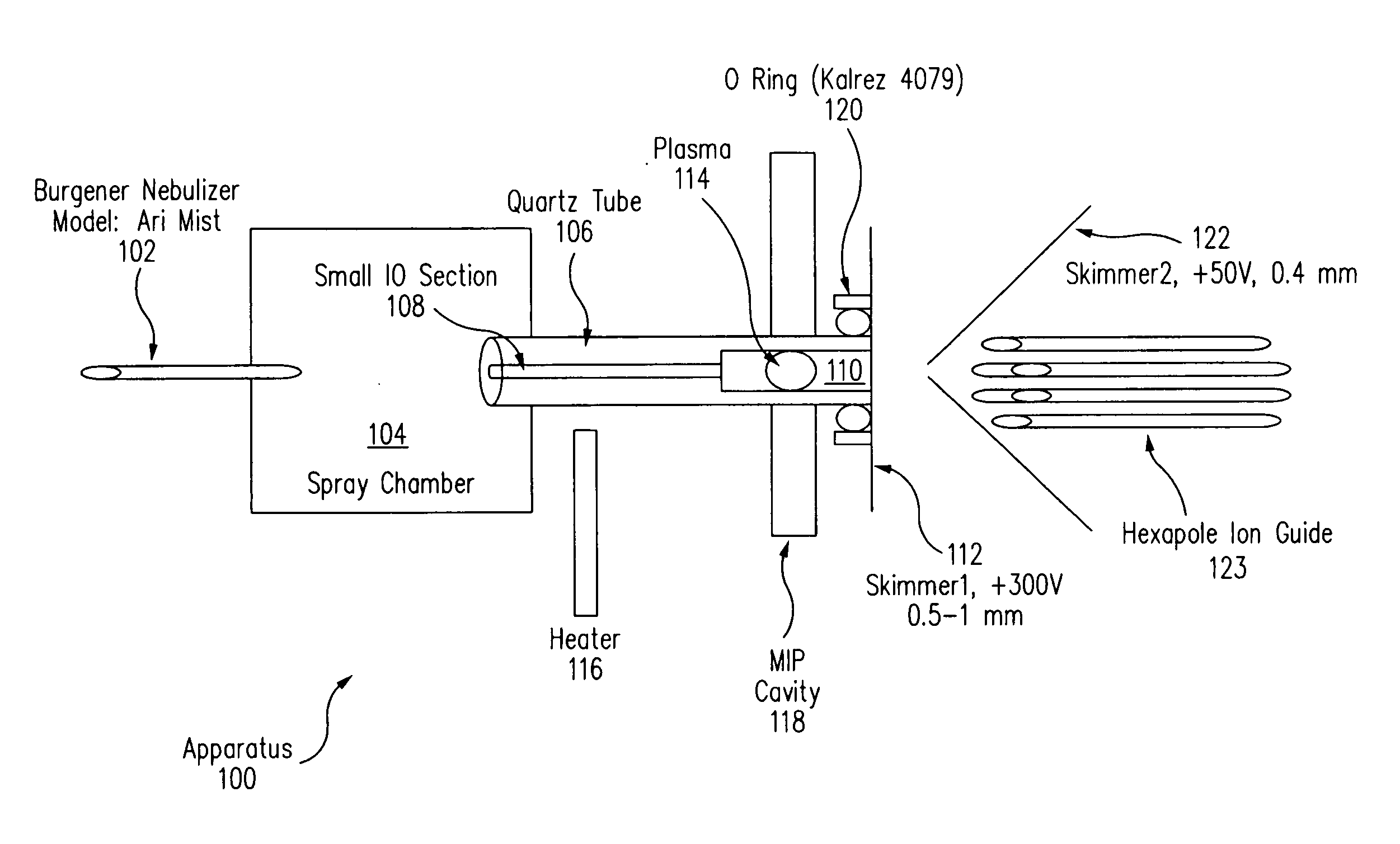
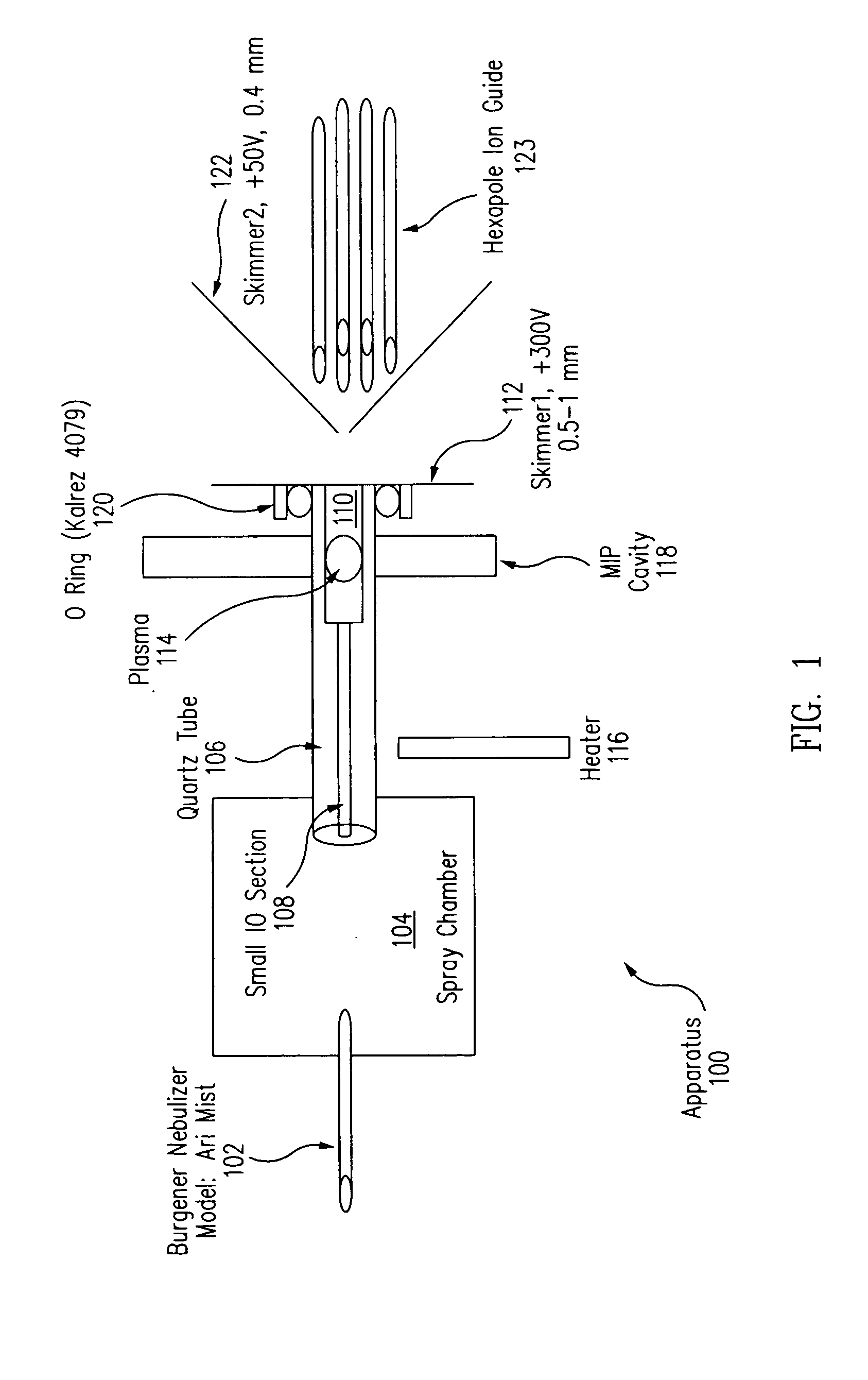
[0032]FIG. 1 is a diagram showing a portion of an apparatus 100 for analyzing gases and chemical solutions according to one embodiment of the present invention. Apparatus 100 includes an electrospray needle or nebulizer 102 that directs nebulized liquid into a sample introduction or spray chamber 104 at atmospheric pressures. In one embodiment, spray chamber 104 may be filled with helium and an aerosol that could be highly acidic. Electrospray needle 102 may be one built by Analytica of Branford or may alternatively be a Burgener nebulizer (e.g., an Ari Mist model), in which the electrospray is used as an atomizer and is not energized electrically. The nebulized liquid is drawn from a sample of solution to be analyzed, such as a SC2 or UPW bath. The nebulized aerosol is formed by combining a carrier gas, such as argon, helium, or nitrogen, with the analyte to form a spray.

[0033] In one embodiment, the pressure of the carrier gas as it is introduced into electrospray needle 102 is appr


PUM


Abstract

A combination electrospray/microwave induced plasma (MIP) ionization source is used as the ionization source for a mass spectrometer. The electrospray can be operated in positive mode, negative mode, or it can be switched off. The microwave-induced plasma can also be switched on or off. This allows the instrument to be operated in multiple modes. With the electrospray off and the MIP on, the instrument will normally have its maximum elemental sensitivity. Mixed mode operation potentially allows the determination of additional information about the chemical constituents present in the analyte. In pure electrospray mode, it is possible to obtain molecular information and to analyze organic compounds.

Description


Claims


Application Information

Patent Timeline
Owner METARA
Why Eureka
Try Eureka