Antenna unit

a technology for antennas and parts, applied in antennas, antenna details, movable bodies, etc., can solve the problem of difficult to correspond to plastic attachment parts with bolts

Inactive Publication Date: 2005-10-13
MITSUMI ELECTRIC CO LTD
View PDF9 Cites 24 Cited by
  • Summary
  • Abstract
  • Description
  • Claims
  • Application Information

AI Technical Summary

Benefits of technology

This patent proposes a way to attach an antenna unit to a plastic material without making it bigger than necessary for its placement on a metal surface. Additionally, this design allows for a more cost-effective solution with different types of mounting options like bolts or adhesives.

Problems solved by technology

This patent describes various technical solutions for improving the performance of car navigation systems and wireless communication systems. One solution involves attaching a receiver antenna to a metal plate called a roof or trunk made of plastic instead of metal. Another solution involves securing the antenna to the roof through bolts or nuts. These techniques have drawbacks such as requiring holes in the roof or trunk, increasing its size, and being expensive due to the materials needed. Additionally, if the antenna is attached directly to the roof without a ground plate, the antenna may not function properly when installed on plastic parts.

Method used


Image

  • Antenna unit
  • Antenna unit
  • Antenna unit

Examples


Embodiment Construction

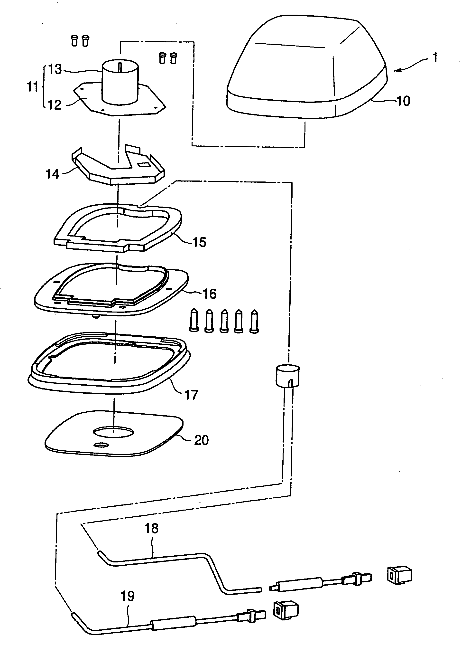
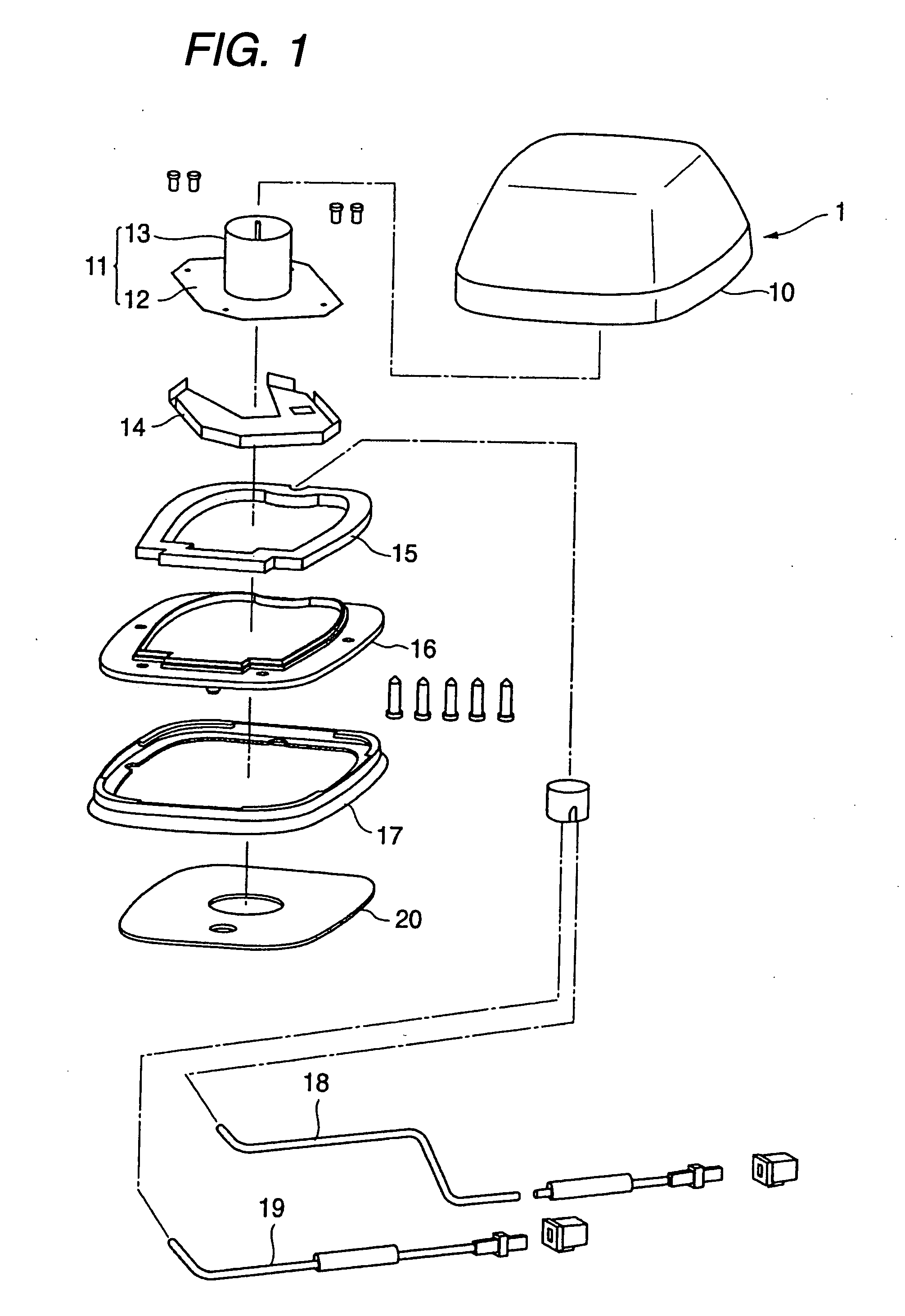
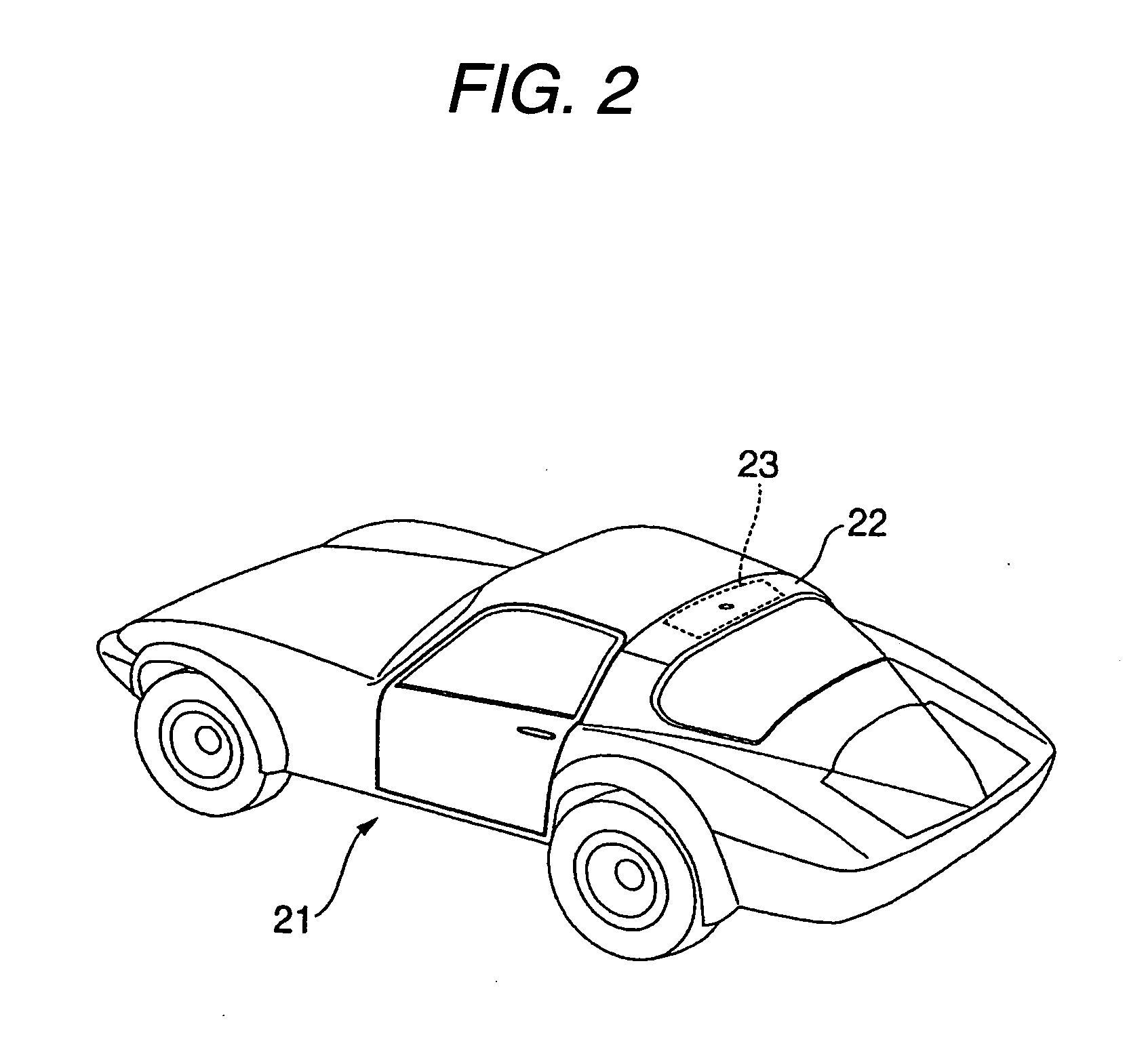
[0021] Regarding an antenna unit to which the invention is applied, attachment of a satellite radio reception antenna onto an automotive roof will be described below as an example.

[0022] A satellite radio reception antenna 1, as shown in FIG. 1, has a cover member 10 of which the whole shape is nearly trapezoid. The cover member 10 is formed by injection molding a resin material having the desired atmospheric corrosion resistance and waterproofing, and the member 10 has inner space which houses each part of the satellite radio reception antenna 1. Further, the cover member 10, of which one surface is opened, is formed in the shape of a bowl. Further, by applying a color sheet printing onto an outer surface of the cover member 10, the color of antenna appearance can be changed variously, so that the user can select an antenna according to color of a car body.

[0023] In the inner space of the cover member 10, an antenna module 11 for receiving radio waves sent from a satellite is housed


PUM


Abstract

An antenna unit includes an antenna module that receives radio waves sent from a satellite or earth, a cover member that has enough inner space to house the antenna module and has an opened bottom surface, and a bottom plate that closes the opened bottom surface of the cover member, and the antenna unit is attached to a resin-made attachment part. A metal sheet is provided on a back surface side of the resin-made attachment part, and the antenna unit is adhesive bonded and fixed on a surface side of the resin-made attachment part correspondingly to an arrangement position of the metal sheet.

Description


Claims


Application Information

Patent Timeline
Owner MITSUMI ELECTRIC CO LTD
Why Eureka
Try Eureka