Capacitive pressure sensor and method of manufacture

Inactive Publication Date: 2005-10-20
ROBERT BOSCH GMBH
View PDF3 Cites 25 Cited by
  • Summary
  • Abstract
  • Description
  • Claims
  • Application Information

AI Technical Summary

Benefits of technology

[0007] The pressure sensor according to the present invention has the advantage that it allows temperature ranges to be entered, which have so far been inaccessible to silicon pressure sensors.
[0008] Furthermore, it is advantageo

Problems solved by technology

Disadvantageous in these sensors is the fact that a high current is required for measuring the resistance, which results in an unnecessarily high power consumption, and that the piezoresistive effect is highly temperature-dependent, which causes problems especially in high-temperature applications.
The above-mentioned capacitive pressure sensors, however, have the disadvantage that for contacting the electrodes configured as diaphragms processes are required which penetrate very deeply into the material of the substrate.
This does not allow for simple implantations.
In addition, wires near the surface

Method used


Image

  • Capacitive pressure sensor and method of manufacture
  • Capacitive pressure sensor and method of manufacture
  • Capacitive pressure sensor and method of manufacture

Examples


Embodiment Construction

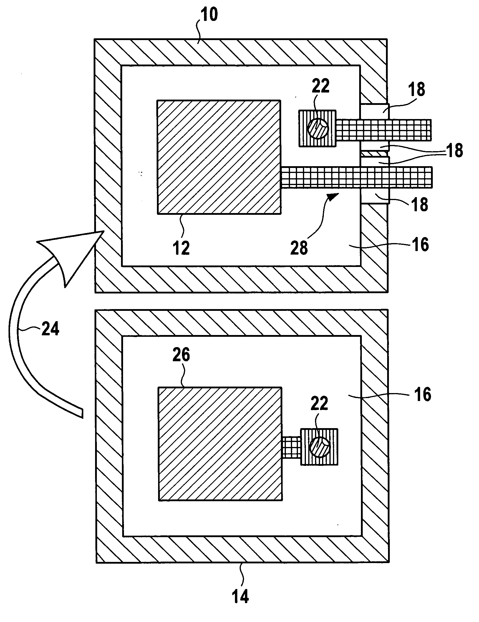
[0011] The core of the present invention is the manufacture of a capacitive pressure sensor 100, shown in FIG. 3, from two wafers bonded together using SOI technology, which is suitable for extreme temperature requirements and additionally allows for the integration of electronics suitable for high temperatures.

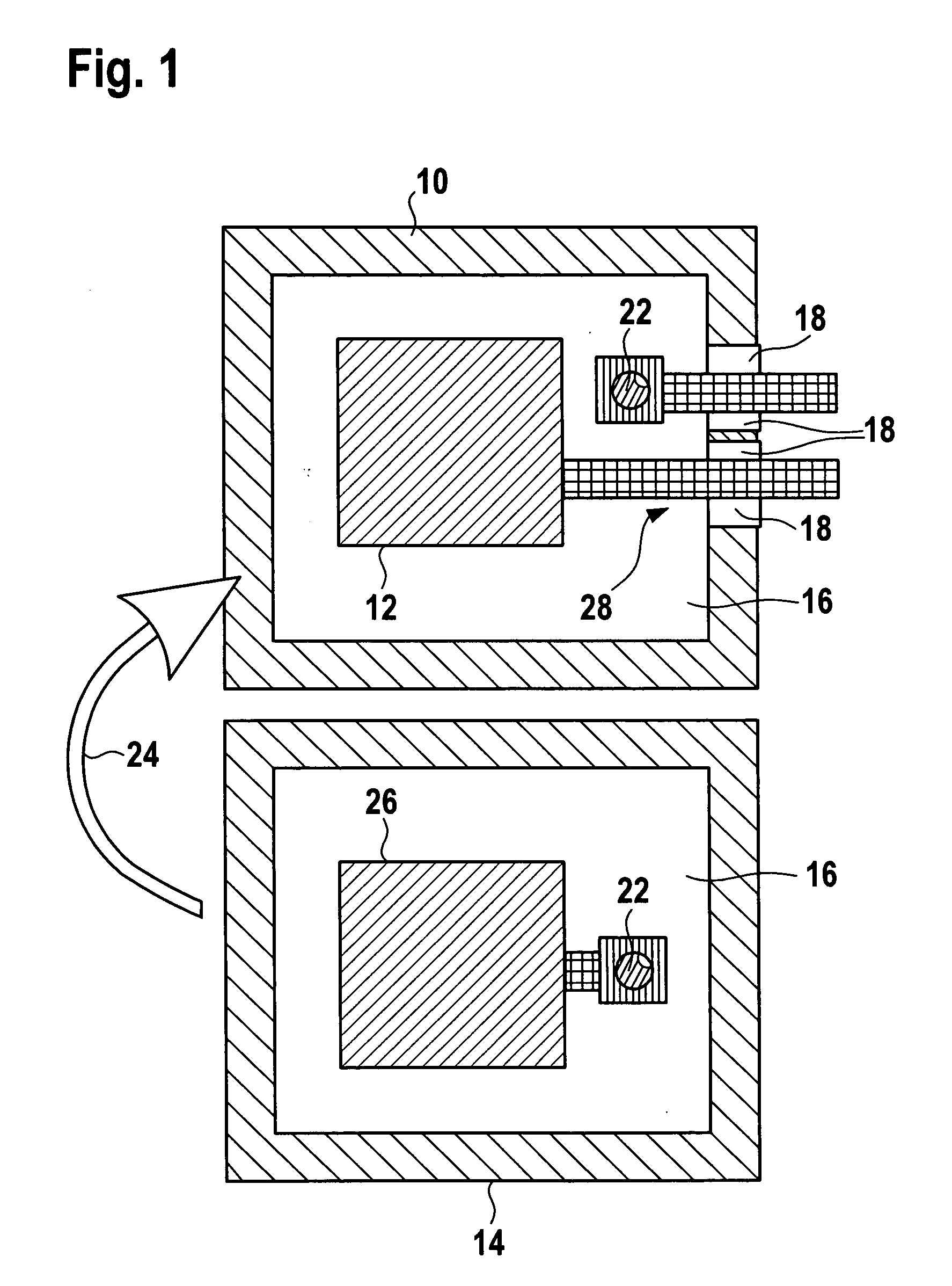
[0012] As can be seen from FIG. 1, first two SOI wafers 10, 14 are processed separately of each other and are subsequently joined together using a flip-chip process (arrow 24 in FIG. 1). In the process, the first wafer (electronics wafer 10, lower electrode 12), which supports the later evaluation circuits 20, is patterned by a conventional microelectronics process, supplemented by the trench etching of the capacitive electrode.

[0013] The steps for patterning evaluation circuits 20 follow currently existing technologies. This applies to the patterning of the amplifier circuit and passive integrated elements. In addition there is the process step for the lateral insulation of t


PUM


Abstract

A capacitive pressure sensor made up of two silicon on insulator (SOI) wafers lying opposite of each other and joined to each other in a vacuum-tight manner, a recess being formed between the two wafers. The first wafer exclusively supports the evaluation circuits required for measuring the applied pressure and a capacitive electrode, and the second wafer has a recess formed by surface micromechanics processes, in which the counter electrode to the capacitive electrode of the first wafer is situated. The second wafer at the same time forms a cover for the first wafer.

Description


Claims


Application Information

Patent Timeline
Owner ROBERT BOSCH GMBH
Why Eureka
Try Eureka