Illuminating device with heat-dissipating function

Inactive Publication Date: 2005-11-17
HUANG KUN LIEH
View PDF3 Cites 106 Cited by
  • Summary
  • Abstract
  • Description
  • Claims
  • Application Information

AI Technical Summary

Benefits of technology

[0006] An object of the present invention is to provide an il

Problems solved by technology

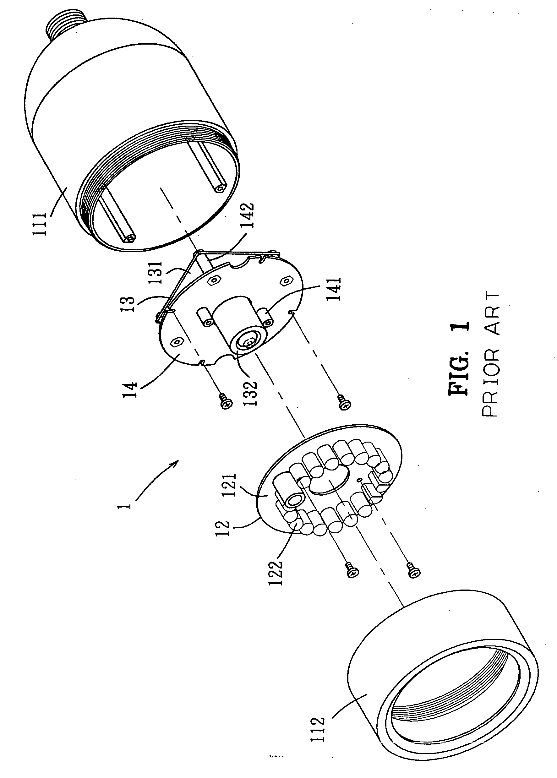
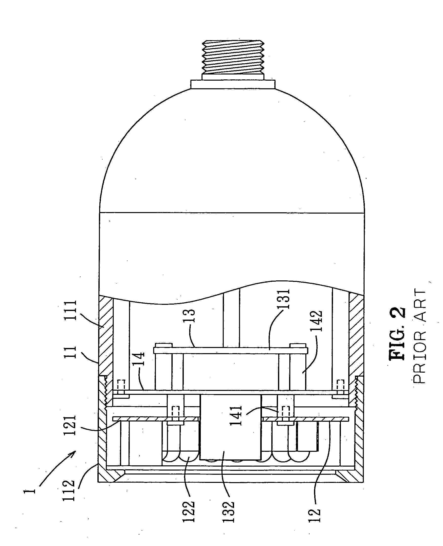
In particular, the generated heat transmitted to the circuit board 121 via the pins of the LEDs 122 or the other electric elements could not be effectively dissipated, as the sealed space of the housing 11 and the circuit board 121 made of glass fiber could not provide a satisfactory heat conduction effect.
The overall heat-dissipating efficiency is poor, resulting in high temperature when the illuminating module 12 operates.
Even worse

Method used


Image

  • Illuminating device with heat-dissipating function
  • Illuminating device with heat-dissipating function
  • Illuminating device with heat-dissipating function

Examples


Embodiment Construction

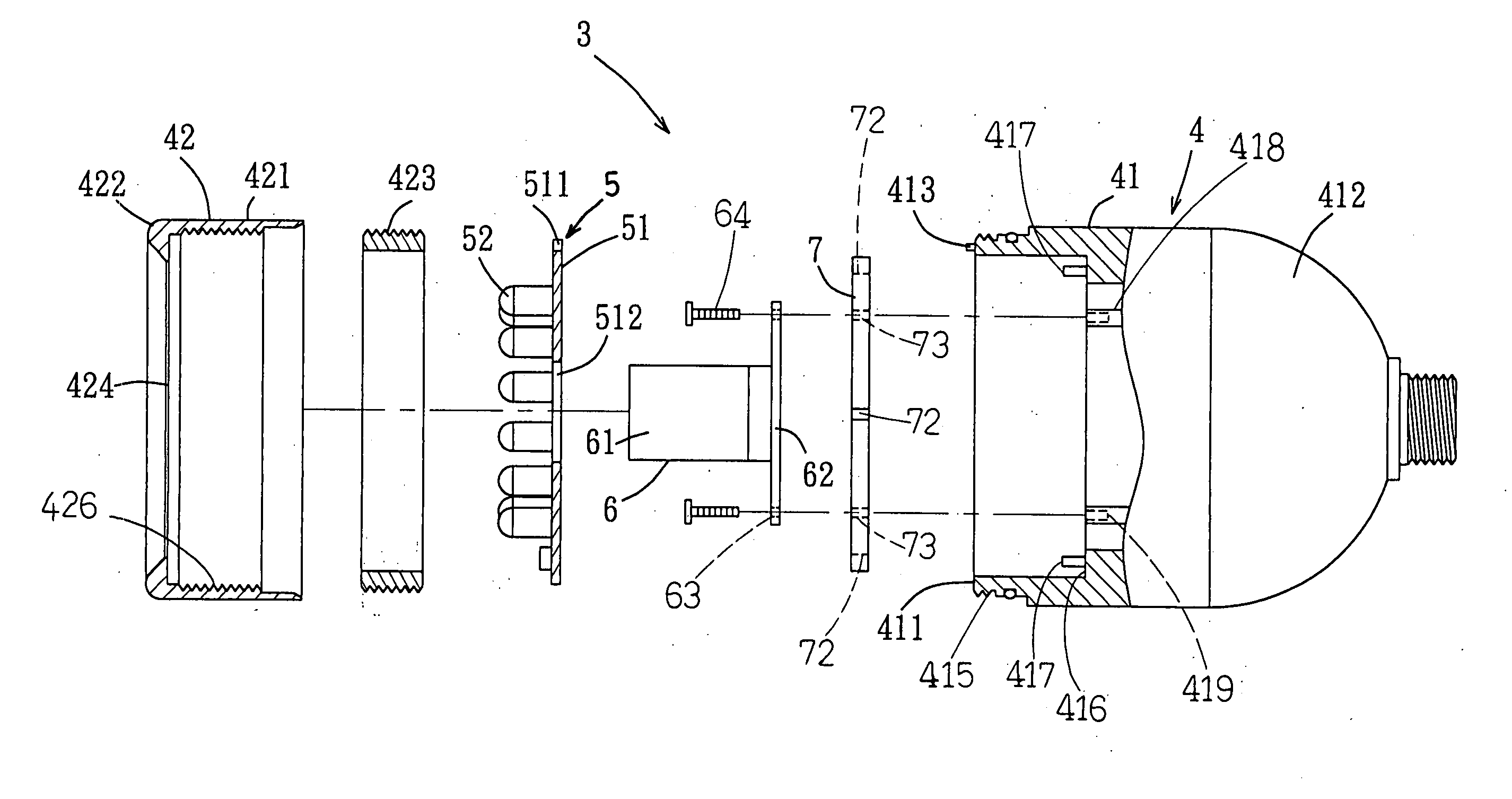
[0029] Referring to FIGS. 3 and 4, an illuminating device 3 in accordance with the present invention comprises a housing 4, an illuminating module 5, and a photographing module 6. The housing 4 include a housing body 41 and a cap 42. The housing body 41 is substantially cylindrical and includes an open first end 411 and a second end 412 tapered to form a smaller opening through which wires (not labeled) for the illuminating module 5 and the photographing module 6 are extended. The open first end 411 of the housing body 41 includes an outer threading 415, and a peg 413 is formed on an end face of the open first end 411.

[0030] The cap 42 is also substantially cylindrical and sized to match the open first end 411 of the housing body 41. In particular, the cap 42 includes a first end 421, a second end 422, and an inner threading 426 for threadedly engaging with the outer threading 415 of the housing body 41. A glass 424 is fixed by a retainer ring 423 to an inner side of the second end 42


PUM


Abstract

An illuminating device includes a housing and an illuminating module mounted in the housing. The housing defines a sealed space that includes a light-transmitting plane on an end thereof. The illuminating module includes a circuit board and lighting elements mounted on the circuit board. The housing includes a housing body and a cap. The housing body includes an open first end, and the cap is mounted to and covers the open first end of the housing body, with the circuit board of the illuminating device being sandwiched between an engaging area between the cap and the housing body. Thus, the heat generated by the illuminating module can be conducted to the housing, providing improved heat-dissipating effect.

Description


Claims


Application Information

Patent Timeline
Owner HUANG KUN LIEH
Why Eureka
Try Eureka