Coupler

a coupler and female technology, applied in the field of female couplers, can solve the problems of excessive force on the pawl operator, adversely affecting human beings, and inability to operate during supply, and achieve the effect of high reliability and convenient operation

Inactive Publication Date: 2006-03-30
KK TOSHIBA
View PDF8 Cites 6 Cited by
  • Summary
  • Abstract
  • Description
  • Claims
  • Application Information

AI Technical Summary

Benefits of technology

This patented invention provides a female coupler that has two parts: one part is easy for users to operate while still being securely attached to it. Another part is designed with multiple components that work together well when connected correctly.

Problems solved by technology

The technical problem addressed by this patent is how to provide a safe and efficient way to deliver cells safely without causing any issues like leaks or accidental use due to insufficient safety measures.

Method used


Image

  • Coupler
  • Coupler
  • Coupler

Examples


Embodiment Construction

[0041] With reference to the drawings, description will be given below of a coupler according to an embodiment of the present invention.

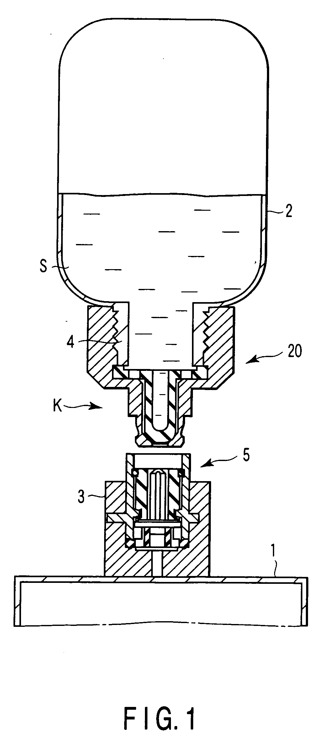
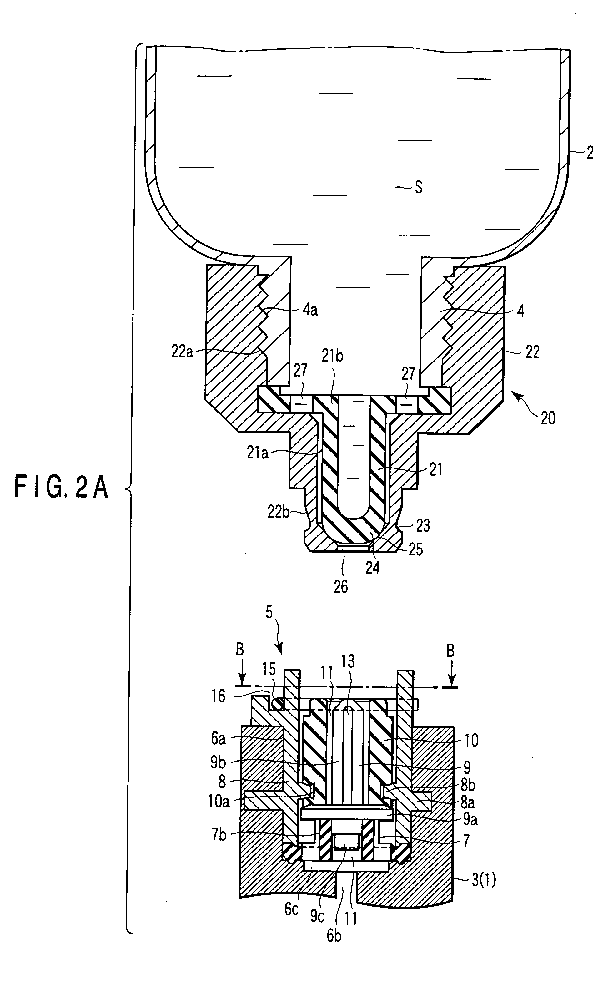
[0042]FIG. 1 shows the configuration of a fuel cell coupler K in a position in which, for example, a cell solution S is supplied.

[0043] Reference numeral 1 at the bottom of FIG. 1 denotes a cell container (solution tank) constituting a fuel cell. Reference numeral 2 at the top of FIG. 1 denotes a supply container (liquid retaining container) in which the cell solution S is stored. When the cell solution S from the supply container 2 is supplied to the cell container 1, the supply container 2 takes a position shown in FIG. 1. However, in a normal state, the supply container 2 is maintained in a position in which it is turned upside down.

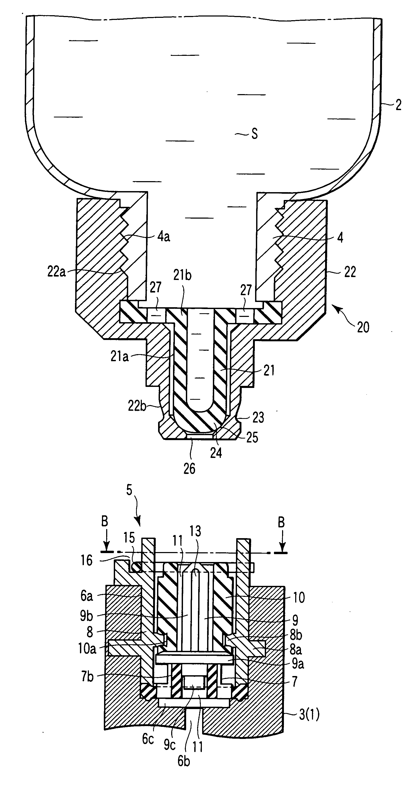
[0044] An injection port 3 is projected from the upper end of the cell container 1. A supply port 4 is projected from the lower end of the supply container 2 in FIG. 1. A female coupler 5 is attached to the injection


PUM


Abstract

A female coupler comprises a valve support accommodated in a hole portion of the injection port and comprising a projecting portion having a axial hole, a cylindrical coupler main body placed around the projecting portion and comprising a locking projecting portion on an inner peripheral surface, a part of the main body being embedded in the injection port so as to have its position fixed, a base valve accommodated in the main body and having an fitting insertion portion inserted into the axial hole and a valve seat portion placed on the projecting portion, the fitting insertion portion and the valve seat portion being connected together, a bar-like portion projected from the valve seat portion and having valve grooves formed on a peripheral surface, and an deformable packing member placed on the valve seat portion and accommodating the bar-like portion, the packing member being fixedly retained in the main body.

Description


Claims


Application Information

Patent Timeline
Owner KK TOSHIBA
Why Eureka
Try Eureka