Parallel shift transmission and method for controlling it

a technology of parallel transmission and transmission input shaft, which is applied in the direction of gearing control, belt/chain/gearing, toothed gearing, etc., can solve the problems of transmission input shaft bearing damage, and achieve the effect of preventing or reducing the service life of the drive train and being less expensiv

Inactive Publication Date: 2006-04-27
SCHAEFFLER TECH AG & CO KG
View PDF5 Cites 5 Cited by
  • Summary
  • Abstract
  • Description
  • Claims
  • Application Information

AI Technical Summary

Benefits of technology

In this new technology, there was developed an improved system where two gears were used instead of one. One problem with current systems is caused by high temperatures during use which can cause damage to certain parts on the vehicle's engine. To solve these problems, it proposes adding another mechanism called a shifter between them. By doing this, they could help protect against overheat issues while still allowing smooth operation even at lower speeds.

Problems solved by technology

The technical problem addressed by this patented technology relates to improving the performance and efficiency of automatic transmission systems used in vehicles (such as cars). These systems have different modes of engagement where certain parts can get stuck due to differences in rotational rates caused by changes over road conditions. This could lead to unsafe operating states and reduce component lifespan.

Method used


Image

  • Parallel shift transmission and method for controlling it
  • Parallel shift transmission and method for controlling it
  • Parallel shift transmission and method for controlling it

Examples


Embodiment Construction

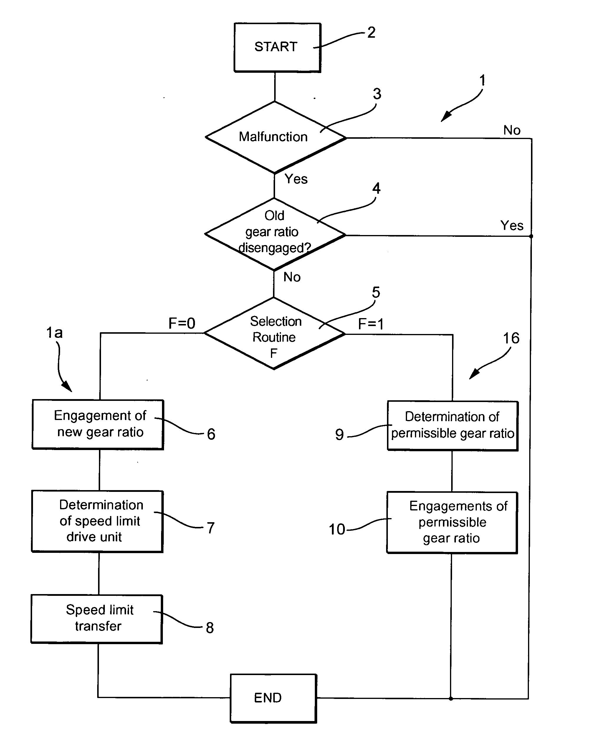
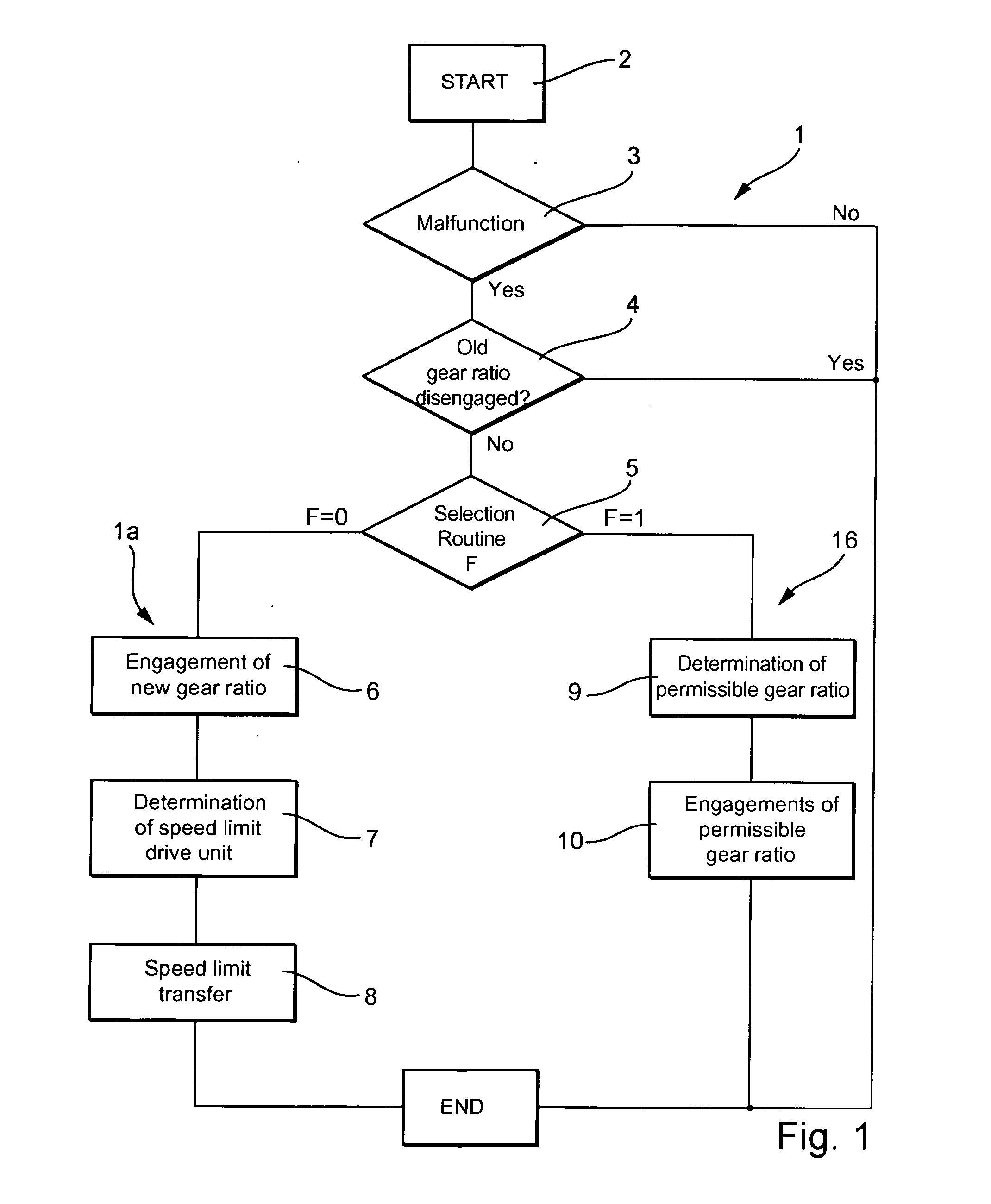
[0014] Method 1 begins with a start condition and a subsequent branch 3 in which a determination is made of whether there is a malfunction of the transmission controller. Such a malfunction may, for example, be the breakage of a shift finger or another component so that an engaged gear ratio step can no longer be disengaged or a jamming of a final control element for engaging or disengaging a gear ratio step so that the transmission actuators provided for this can no longer disengage the gear ratio step. If there is no malfunction, the routine is terminated immediately. In the detection of a malfunction, which may be accomplished, for example, via the evaluation of responses of the transmission actuator to the controller responsible for controlling the transmission, a check is made of whether an engaged gear ratio step has been disengaged. If the gear ratio step that is supposed to be disengaged is disengaged, the routine is terminated. Whether a gear ratio step is still engaged may be


PUM


Abstract

The invention relates to a parallel shift transmission having a drive unit and two partial transmissions, each connectable to the drive unit via a friction clutch and each having a plurality of gear ratio steps.

Description


Claims


Application Information

Patent Timeline
Owner SCHAEFFLER TECH AG & CO KG
Why Eureka
Try Eureka