Fluorescent lamp

a technology of fluorescent lamps and filament lamps, which is applied in the direction of discharge tubes/lamp details, luminescent screens, discharge tubes/lamps, etc., can solve the problems that fluorescent lamps connected in series cannot provide a perfect illumination effect, and achieve the effect of improving the outward appearance and an illumination

Inactive Publication Date: 2006-06-01
FEELUX CO LTD
View PDF3 Cites 0 Cited by
  • Summary
  • Abstract
  • Description
  • Claims
  • Application Information

AI Technical Summary

Benefits of technology

The technical purpose described in this patented technology improves how well fluorescence lights look on when they are lit up or shining down from their standpoint. By adding regular intervals for holding fixtures with different colors, these lights will appear more like natural lighting without any holes that could be seen through them.

Problems solved by technology

Introduction: Fluorescents have many uses that require lights like indoor displays or outdoor signs. These lights use smaller sections called flares instead of larger ones due to their size. To install these types of bulbs into specific locations without causing damage they must meet certain standards set forth during manufacturing process. There currently exist methods where multiple bulb holding frames can be combined together with each other to achieve better results than just having them individually attached.

Method used


Image

  • Fluorescent lamp
  • Fluorescent lamp
  • Fluorescent lamp

Examples


Embodiment Construction

[0024] The present invention will now be described in detail in connection with preferred embodiments with reference to the accompanying drawings.

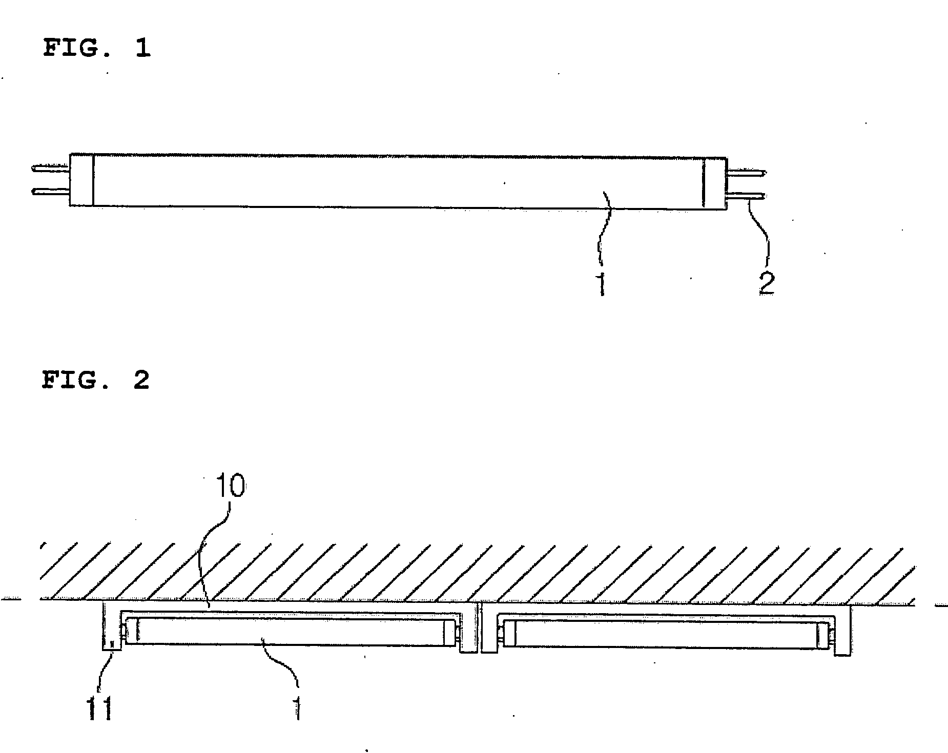
[0025] The same parts as the prior art will not be described.

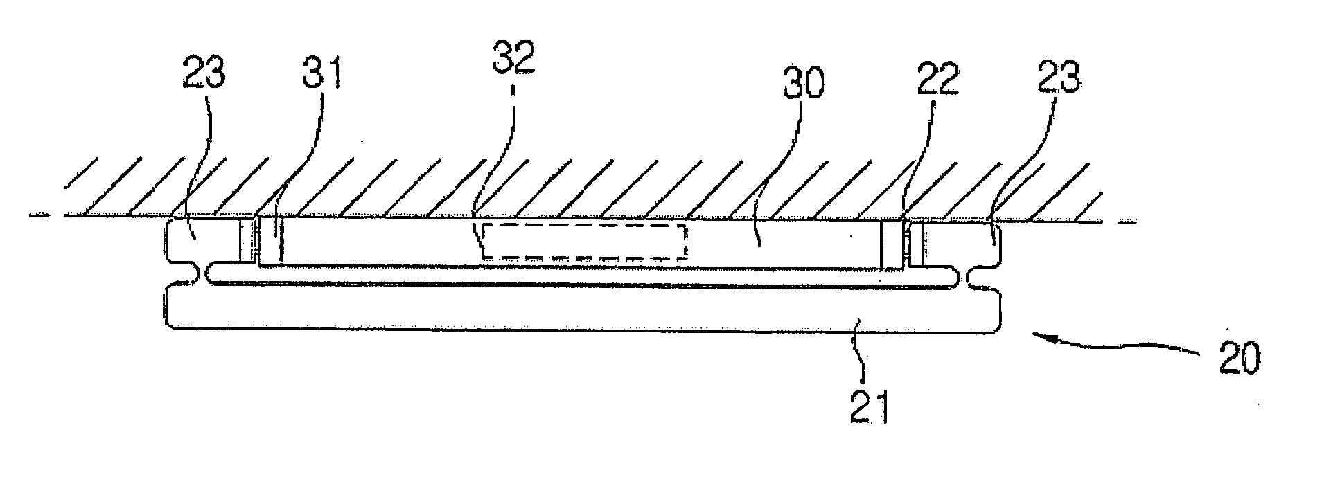
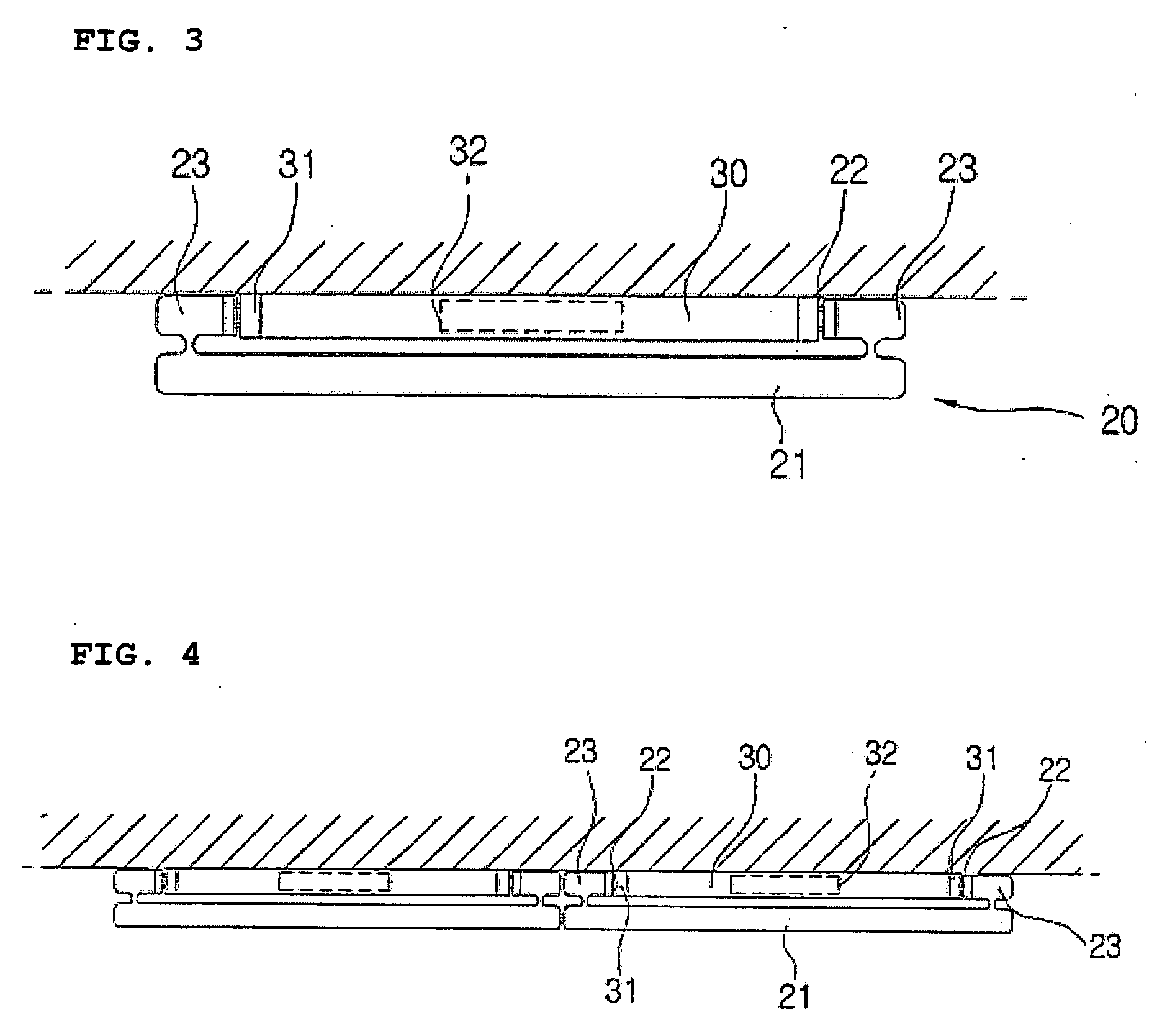
[0026]FIG. 3 is a view of a fluorescent lamp according to a preferred embodiment of the present invention, and FIG. 4 is a view showing a state in which the fluorescent lamps according to the present invention are connected and installed in series.

[0027] The most basic structure of a fluorescent lamp 20 according to the present invention is that a number of the fluorescent lamps 20 are closely arranged not to generate spaces between the fluorescent lamps 20 when the fluorescent lamps 20 are connected in series.

[0028] Additionally, it is important that even though the structure of the fluorescent lamps 20 is changed, the entire volume of the fluorescent lamps 20 is not increased after assembly of the fluorescent lamps 20 with fluorescent lamp holders 30.

[0029] To this end, the f


PUM


Abstract

Disclosed is a fluorescent lamp, which can remove an irregular arrangement of fluorescent lamp holders and prevent break-off of illumination generated at spaces formed between connected fluorescent lamps when the fluorescent lamp holders are arranged in series. The fluorescent lamp includes a tubular lamp body (21); auxiliary tubes (23) extending from both side ends of the tubular lamp body (21); and connection terminals (22) formed inwardly at both side ends of the auxiliary tubes (23). A variety of fluorescent lamp holders for allowing the use of the fluorescent lamp are provided.

Description


Claims


Application Information

Patent Timeline
Owner FEELUX CO LTD
Why Eureka
Try Eureka