Systems for controlling multiple actuators

Inactive Publication Date: 2006-08-10
HALLIBURTON ENERGY SERVICES INC
View PDF22 Cites 18 Cited by
  • Summary
  • Abstract
  • Description
  • Claims
  • Application Information

AI Technical Summary

Benefits of technology

This invention relates to a method or device used with electronic devices such as servers (server computers) where multiple processors are connected together through communication networks like LANs). These network connections allow each computer on one side to communicate data between itself without being affected by any external factors affecting its performance. By having these components work alongside each other well, they can improve overall efficiency and reliability over time.

Problems solved by technology

This patented describes how different types of chemical reactions involve multiple actuating devices with individual limitations affecting their operation. These technical problem addressed by these inventors relates to developing a more efficient way to manage multi-actuator systems while avoiding hard stopping them downstream due to external factors like variations in ambient conditions during production.

Method used


Image

  • Systems for controlling multiple actuators
  • Systems for controlling multiple actuators
  • Systems for controlling multiple actuators

Examples


examples

[0036] The invention having been generally described, the following examples are given as particular embodiments of the invention and to demonstrate the practice and advantages thereof. It is understood that the examples are given by way of illustration and are not intended to limit the specification or the claims to follow in any manner.

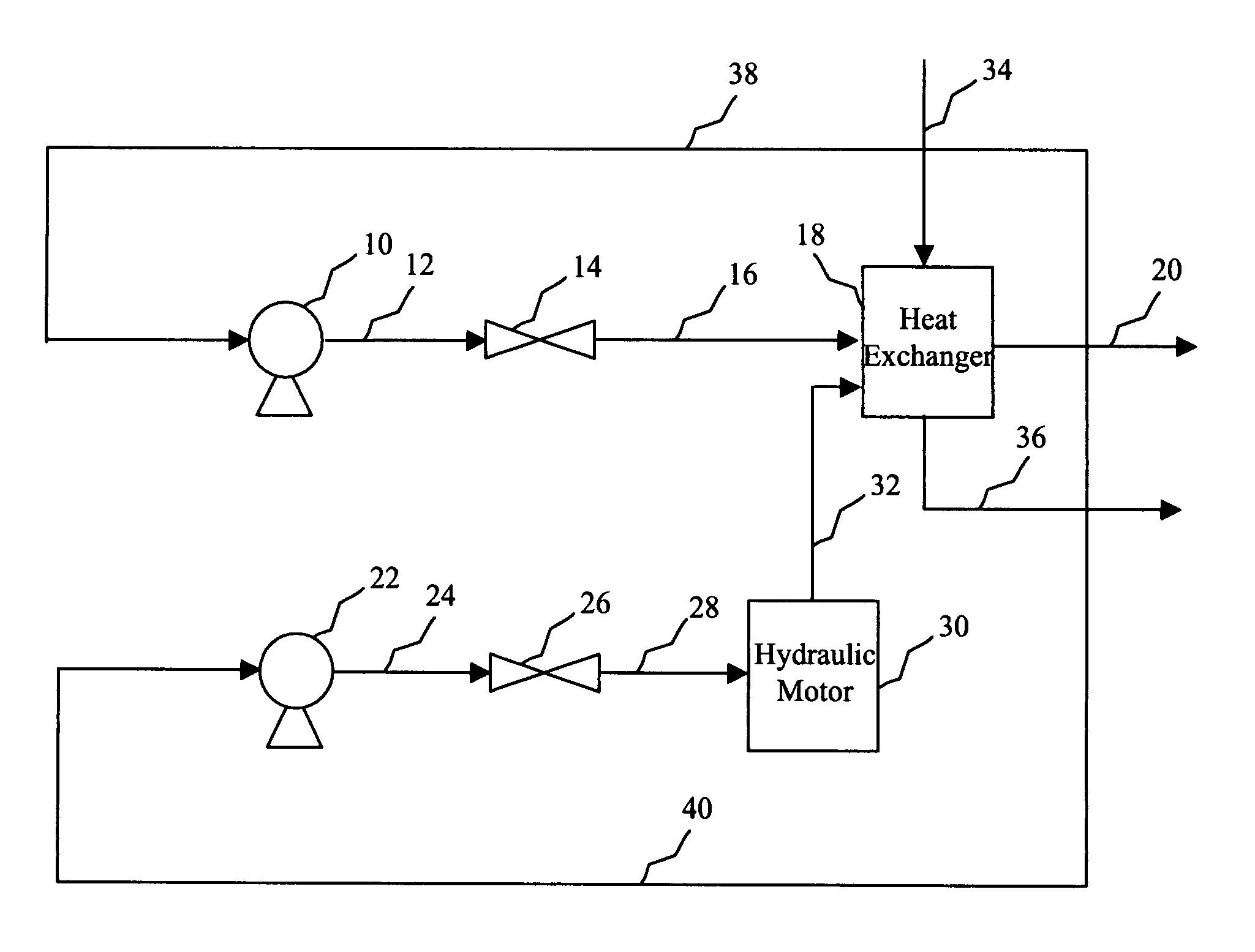
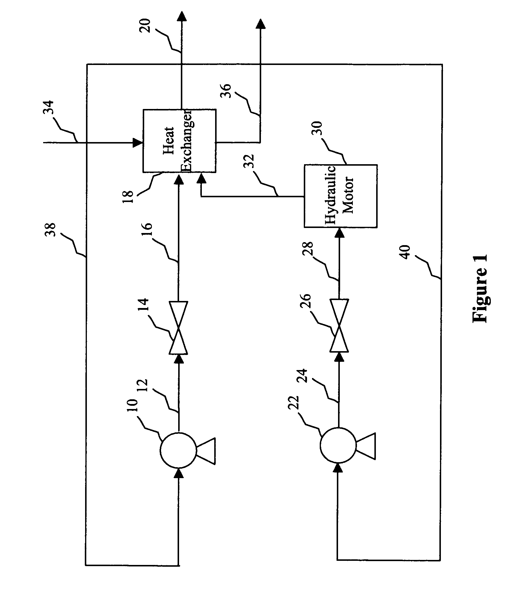
[0037]FIGS. 7-10 illustrate different operations of the heating unit of a nitrogen pumping system like that shown in FIG. 1 using the actuator control system described in this application. Each figure plots various parameters of the heating unit as a function of time. More specifically, in each figure, line 500 represents the change in pressure of the overall system, line 502 represents the change in the position of the cryo valve (i.e., the second actuator), line 504 represents the change in the cryo valve pressure, line 506 represents the change in the position of the hydraulic heater valve (i.e., the first actuator), and line 508 represents the cha


PUM


Abstract

Methods, control systems, and information handling systems for controlling at least two actuators are provided. An internal control system sends an input received from the main control system to a first actuator and diverts a portion of the input to a second actuator when an input constraint of the first actuator is reached. The actuators may be throttle valves for heating a hydraulic line. The internal control system includes a cutoff rerouter for implementing the sending and the diverting of the input and an adaptive cutoff controller, e.g., an integral controller, for determining the input constraint of the first actuator. The information handling systems include a determination logic for determining if an input received from the main control system is greater than an input constraint of the first actuator and a diverting logic for diverting a portion of the input to a second actuator when the input is greater.

Description


Claims


Application Information

Patent Timeline
Owner HALLIBURTON ENERGY SERVICES INC
Why Eureka
Try Eureka