Half-open position holding apparatus for vehicle opening and closing member

a technology of holding apparatus and vehicle, which is applied in the direction of motor/generator/converter stopper, dynamo-electric converter control, roof, etc., can solve the problems of increasing power consumption of in-vehicle battery and reducing life, so as to prevent the omission of closing the opening and closing member, prevent current, prevent excessive discharging of in-vehicle battery

Active Publication Date: 2006-10-19
MITSUI KINZOKU ACT
View PDF5 Cites 16 Cited by
  • Summary
  • Abstract
  • Description
  • Claims
  • Application Information

AI Technical Summary

Benefits of technology

This patent describes a system where a problem with the power supply of an electric car's batteries occurs if they are left unattended while parked at an incline or other inclining surface. When this happens, it causes the openings and closures of the car's charging equipment to move upwards towards their closed positions without receiving enough power. To solve this issue, the system uses a timer to stop the movement until the next time the charger starts delivering power again. By doing this, the battery will continue to work properly even if there were any issues with its ability to connect to another device.

Problems solved by technology

The technical problem addressed in this patent is how to stop a sliding door in a way that prevents it from tilting too much while still allowing it to move smoothly without any issues like getting stuck or causing damage.

Method used


Image

  • Half-open position holding apparatus for vehicle opening and closing member
  • Half-open position holding apparatus for vehicle opening and closing member
  • Half-open position holding apparatus for vehicle opening and closing member

Examples


first embodiment

(First Embodiment)

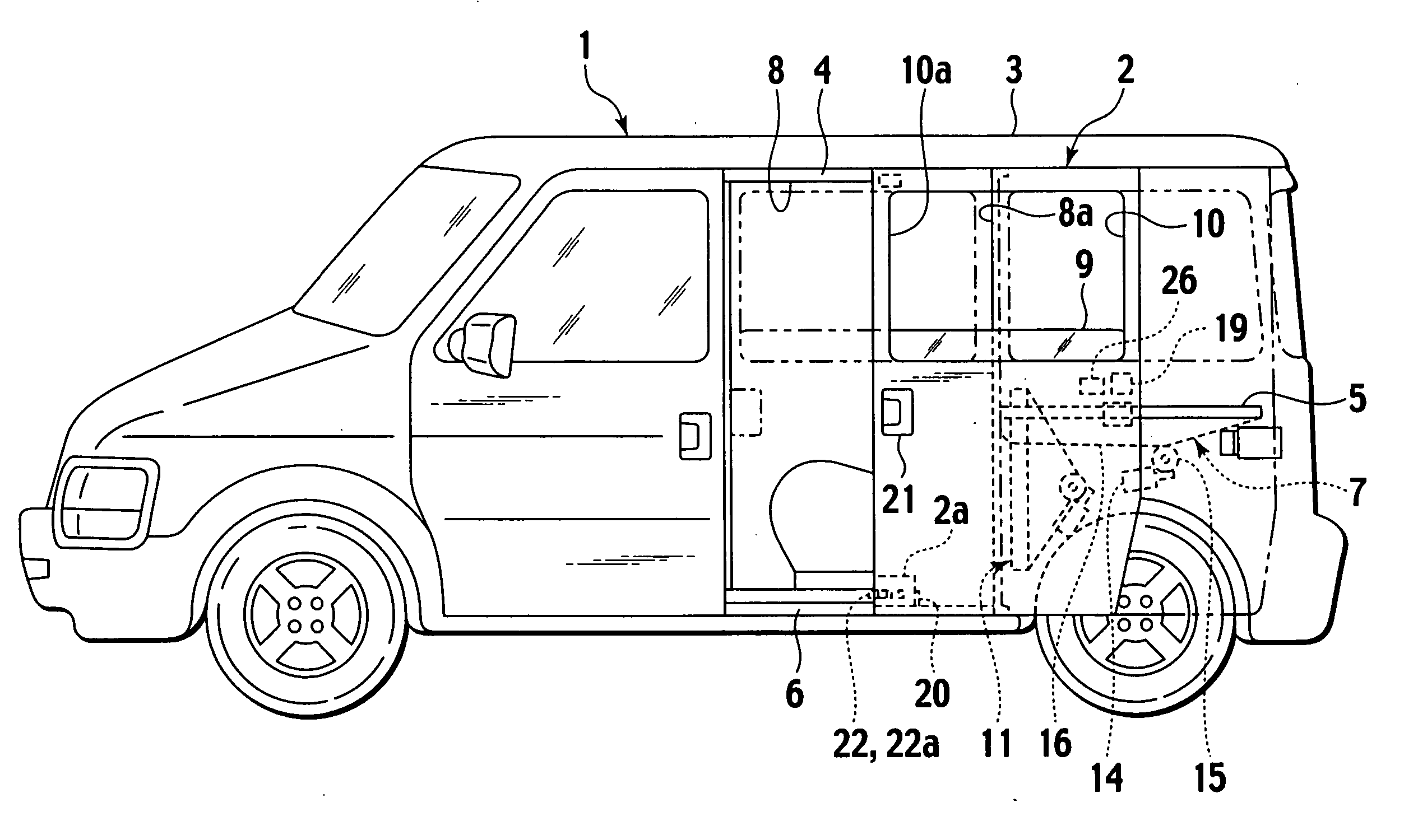
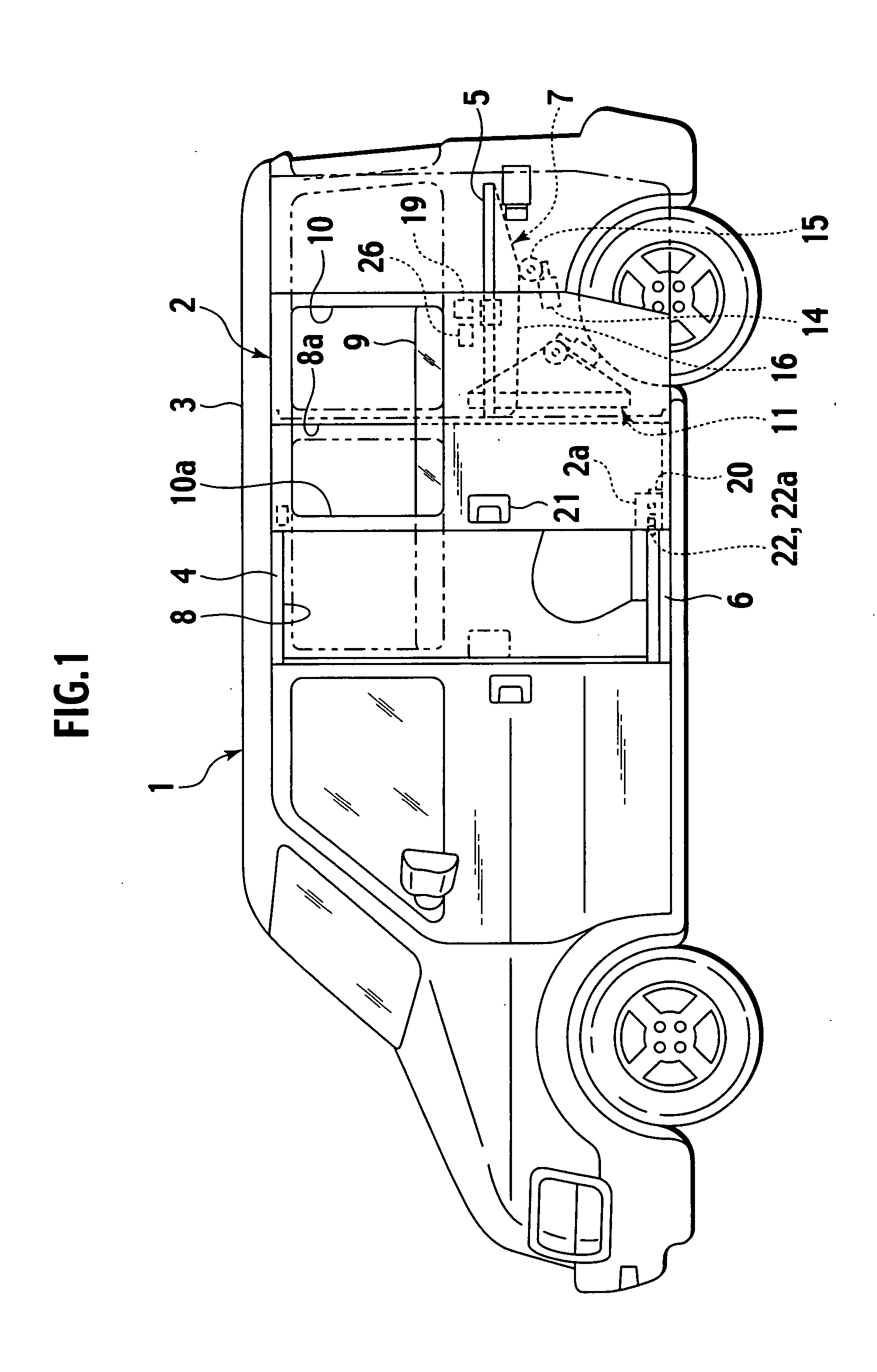
[0028] The first embodiment of the invention will be explained below with reference to the drawings. FIG. 1 is a side view of a vehicle according to the first embodiment of the invention. In the following explanation, a leftward direction in FIG. 1 denotes “front”, while a rightward direction in FIG. 1 denotes “rear”.

[0029] A sliding door 2 constitutes an opening and closing member of a vehicle 1 of a mini-van or a wagon type, and it is supported to be openable and closable in front and rear directions by guide rails 4, 5, and 6 fixed to an upper portion, a middle portion, and a lower portion of a vehicle body 3 to extend in a horizontal direction. The sliding door 2 can be moved from a fully-closed position where a door entrance 8 provided in an outside face of the vehicle body 3 has been closed to a fully-opened position where the sliding door 2 has been moved rearward along the side face of the vehicle body 3, while the sliding door 2 is being moved slightly from

second embodiment

(Second Embodiment)

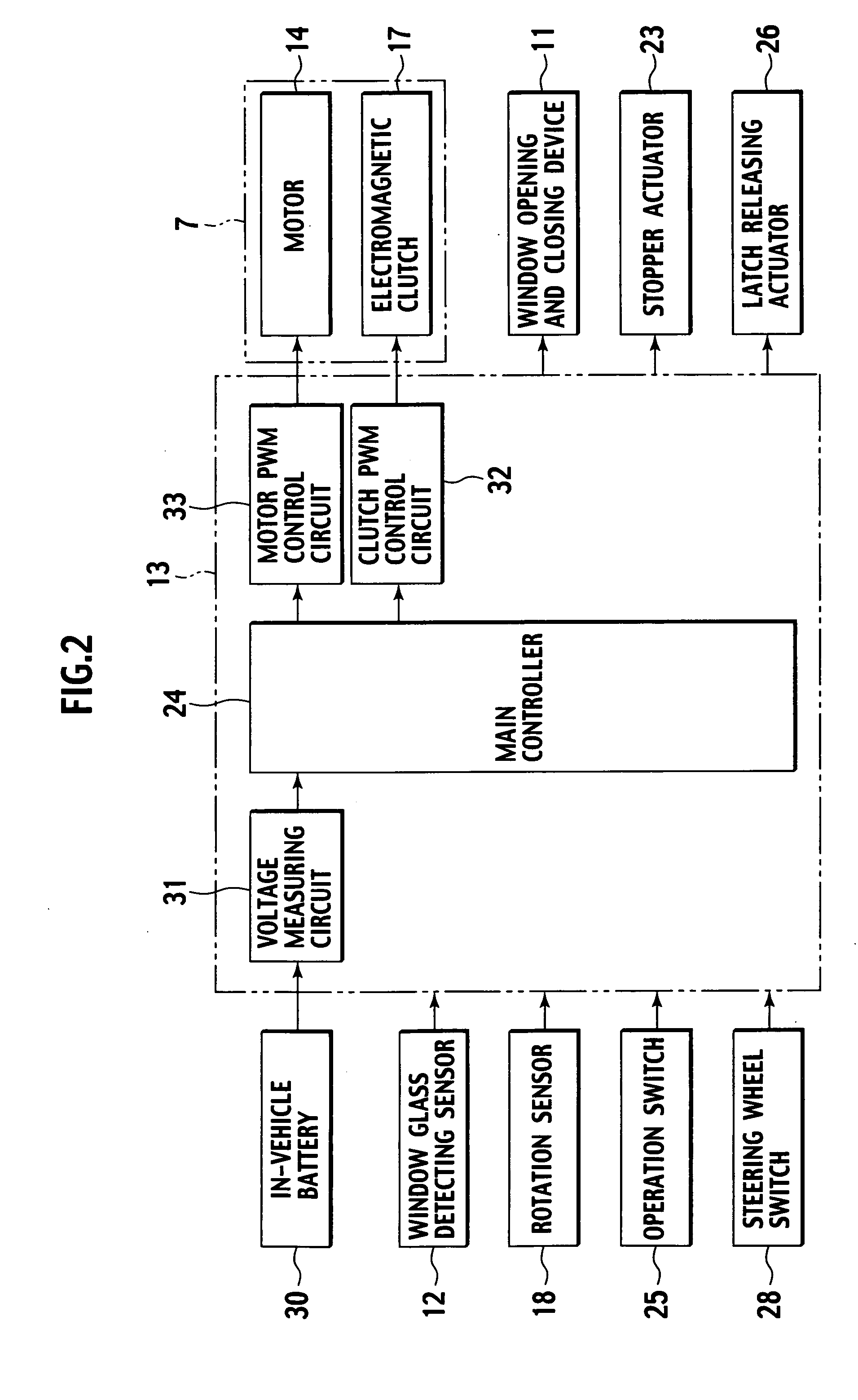
[0069]FIG. 3 is a block diagram of a control circuit according to a second embodiment of the present invention. A main control unit 24 in the second embodiment calculates a duty ratio such that current flowing into the electromagnetic clutch 17 becomes a predetermined flowing current (current flowing through the electromagnetic clutch 17 when a predetermined voltage is applied to the electromagnetic clutch 17) preliminarily set by the current detecting circuit 34 that measures current flowing through the electromagnetic clutch 17 to output a pulse width modulation output signal corresponding to the duty ratio to the clutch PWM control circuit 32 for putting the electromagnetic clutch 17 in the half-open position holding connection state.

[0070] The current flowing through the electromagnetic clutch 17 is proportional to a voltage applied to the electromagnetic clutch 17. Accordingly, by calculating the duty ratio such that the current flowing into the electromagnetic


PUM


Abstract

A half-open position holding apparatus for a vehicle opening and closing member includes an opening and closing member supported in a vehicle body to be openable and closable and has an opening and closing member driving unit that has a motor and a electromagnetic clutch that can put a power transmission path connecting the motor and the opening and closing member in a connected state and in a disconnected state, for driving the opening and closing member in opening and closing directions thereof, and an in-vehicle battery serving as a power source for the electromagnetic clutch. The apparatus includes a controller for controlling the opening and closing member driving unit, that, when the opening and closing member is held at a half-open position between a fully-closed position and a fully-opened position, holds the opening and closing member at the half-open position by stopping the motor, putting the electromagnetic clutch in a connected state, and controlling the electromagnetic clutch to a half-open position holding connection state such that a voltage applied to the electromagnetic clutch becomes a predetermined voltage lower than an output voltage of the in-vehicle battery.

Description


Claims


Application Information

Patent Timeline
Owner MITSUI KINZOKU ACT
Why Eureka
Try Eureka