Carriage and gantry comprising such a carriage

Inactive Publication Date: 2006-11-09
CINETIC LINKING
View PDF1 Cites 3 Cited by
  • Summary
  • Abstract
  • Description
  • Claims
  • Application Information

AI Technical Summary

Benefits of technology

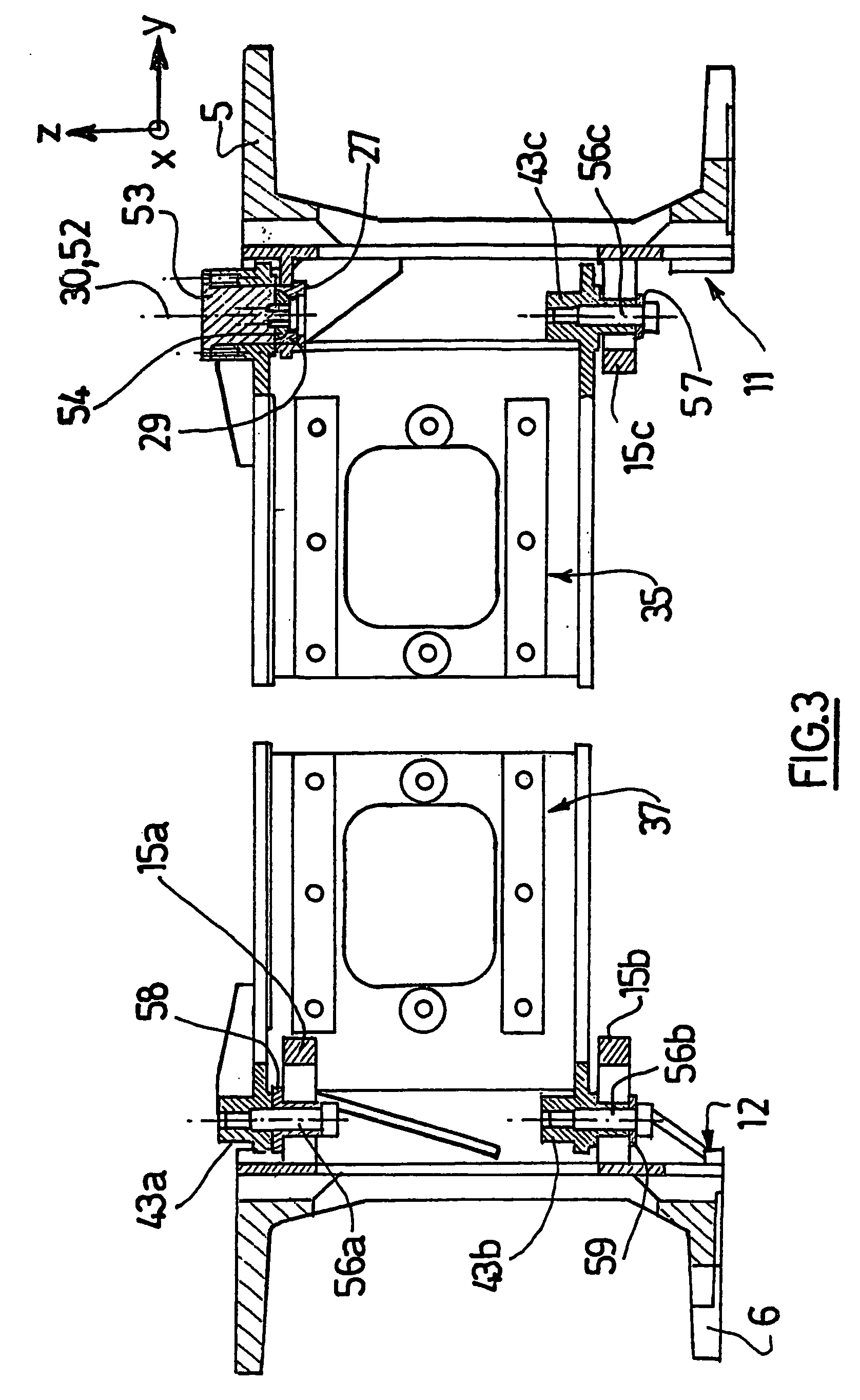
[0011] Because the central girder is not being fixed to the stirrups, the stirrups can move with respect to each other, causing a deformation of the carriage (movement of the central girder with respect to the stirrups). The means of connection between the lateral ends of the central girder and the stirrups makes it possible to acc

Problems solved by technology

However, this solution is technically difficult to implement and may prove to be costly.
Means of synchronising the two motors must then be provided, which gives rise to not insignificant additional cost and requires increased maintenance of the installations.
In addition, despite these synchronisation means, there remain risks that the stirrups may not be moved strictly simultaneously and at the same speed.
As a result the carriage may not remain perfectly transverse and risks being locked aslant between the lateral girders.
In addition, having regard to the imperfect synchronisation of the two stirrups, such gantries do not allow movement of the carriage with the required precision, around one mi

Method used


Image

  • Carriage and gantry comprising such a carriage
  • Carriage and gantry comprising such a carriage
  • Carriage and gantry comprising such a carriage

Examples


Embodiment Construction

[0026] Reference is made first of all to FIG. 1, which depicts a quadratic gantry 1 comprising first and second lateral girders 2, 3 substantially parallel to each other. The girders can have a length attaining 20 to 30 m, and be spaced apart by 5 to 10 m for example. The direction x of the lateral girders 2, 3 is said to be longitudinal, and the orthogonal direction y situated in the plane of the girders is said to be transverse. A third direction z, orthogonal to the other two, is also defined. The direction z is said to be vertical. However, this term is employed only for the purpose of simplification of the description, since the plane formed by the lateral girders 2, 3 may be not horizontal but inclined. A location close to the longitudinal axis situated halfway between the two lateral girders 2, 3 is said to be “internal”, in contradistinction to a location at a distance from this axis, said to be “external”. The terms “top”, “bottom”, “above”, “below”, “high”, “low” will be empl


PUM


Abstract

A carriage is intended to be disposed transversely between essentially-parallel lateral girders. The carriage comprises: stirrups which are disposed at the lateral ends and which each cooperate with a lateral girder in order to enable the movement of the carriage along the longitudinal axis (x) of the lateral girders; a central girder which is placed between the stirrups; first connecting means which are provided between a first lateral end of the central girder and the first stirrup, and second connecting means which are provided between a second lateral end of the central girder and the second stirrup. The aforementioned connecting means are arranged such as to enable the movement of one stirrup in relation to the other with six degrees of freedom and a limited amplitude.

Description


Claims


Application Information

Patent Timeline
Owner CINETIC LINKING
Why Eureka
Try Eureka