Vertically adjustable device for suspending an article from a ceiling

a vertical adjustment and ceiling technology, applied in the direction of screws, nuts, bolts, etc., can solve the problems that the difficulty of reaching an article suspended from a ceiling hook may even be dangerous

Active Publication Date: 2006-12-21
COBRA FIXATIONS CIE COBRA
View PDF7 Cites 0 Cited by
  • Summary
  • Abstract
  • Description
  • Claims
  • Application Information

AI Technical Summary

Benefits of technology

The purpose of this new design for a ceiling fixture is to allow objects like furniture or other items to be easily elevated and lowered by lifting them up on top.

Problems solved by technology

This patent describes a problem with attaching objects like cables to a ceiling hook that cannot easily get out of place during maintenance work without causing damage. Existing solutions involve using tools like screwdrivers or hydraulic lifts, but these methods require physical effort and risk injury.

Method used


Image

  • Vertically adjustable device for suspending an article from a ceiling
  • Vertically adjustable device for suspending an article from a ceiling
  • Vertically adjustable device for suspending an article from a ceiling

Examples


Embodiment Construction

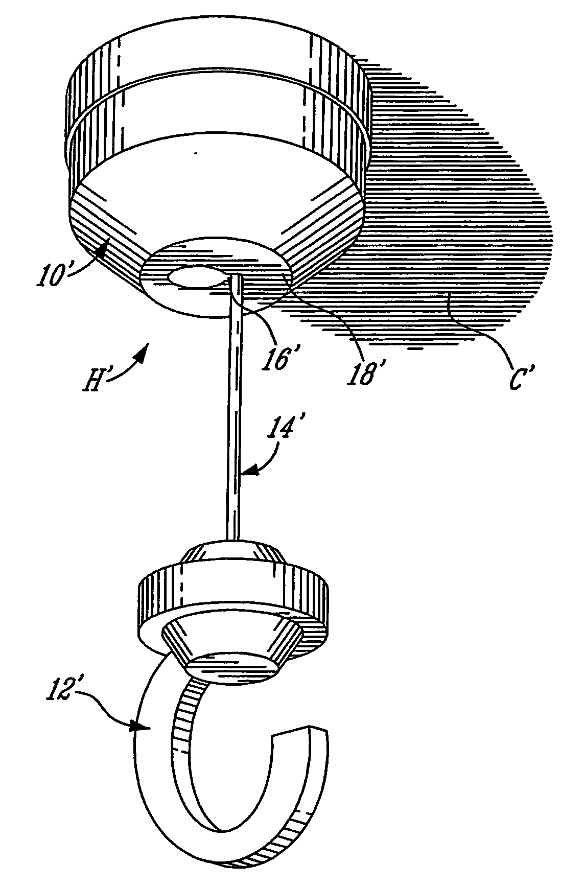
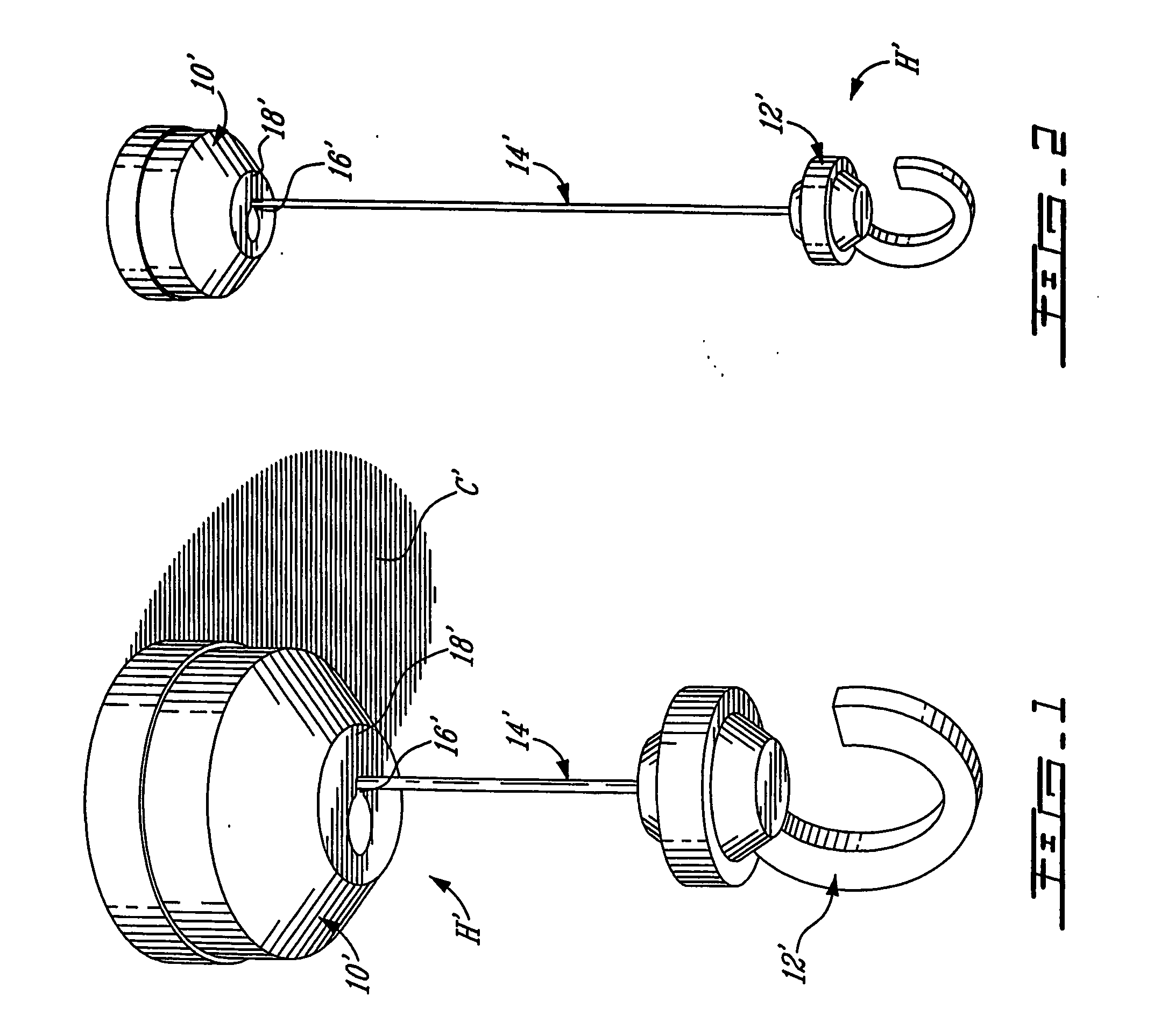
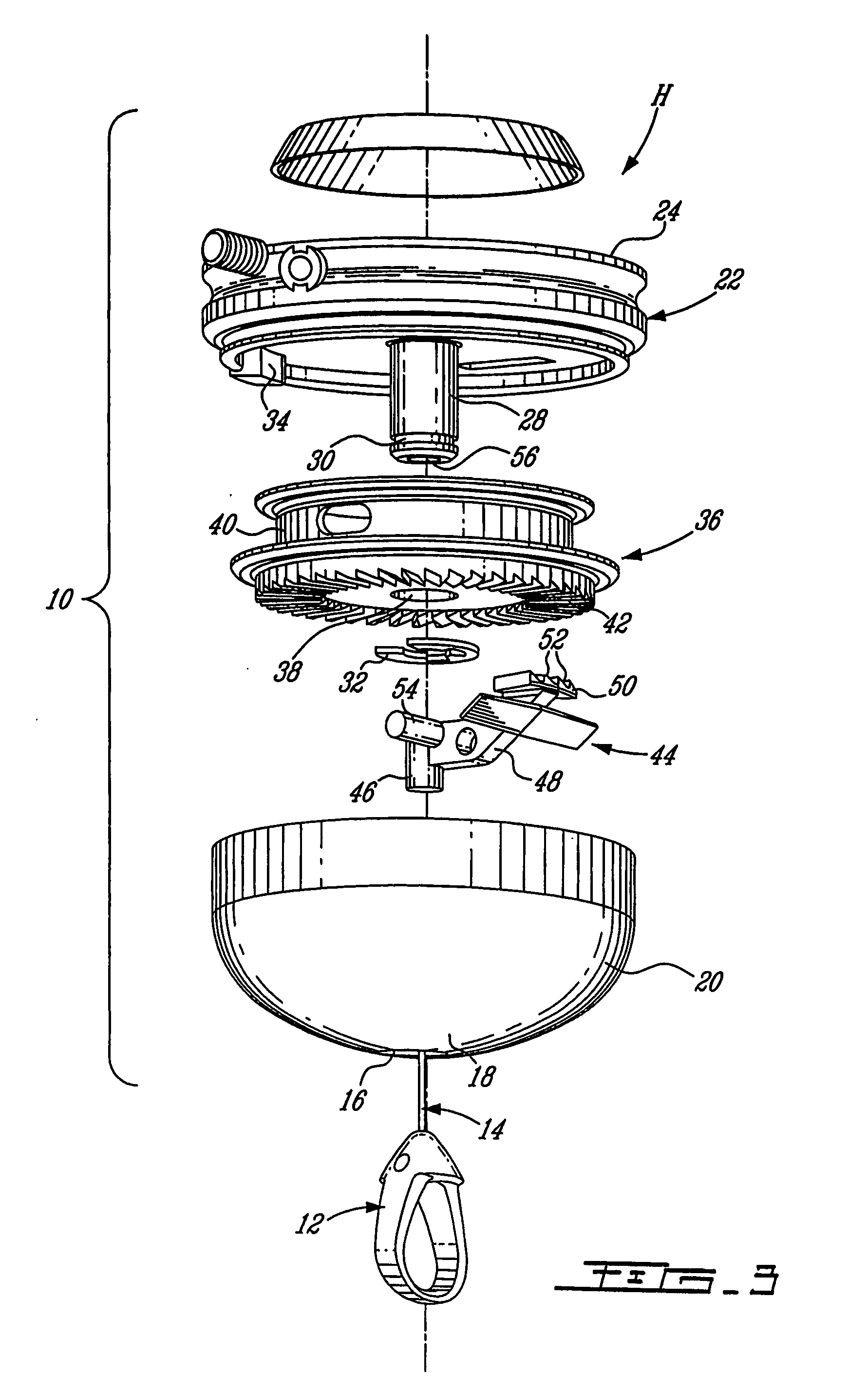
[0053] In accordance with the present invention, FIGS. 1 and 2 illustrate a ceiling hook H′ that comprises a base 10′ adapted to be secured to a ceiling C′, a hook 12′ for suspending articles therefrom, such as planters, and a retractable cable 14′, or the like, that connects the hook 12′ to the base 10′. Generally, a lower end of the cable 14′ is fixedly attached to an upper end of the hook 12′, whereas an upper end of the cable 14′ is secured to a mechanism located inside the base 10′ and adapted to allow the cable 14′ to retract in, or to be extended from, the base 10′, thereby adjusting the elevation of the hook 12′ and thus of the article attached thereto. The base 10′ defines an elongated, e.g. oblong, opening 16′ in a lower wall 18′ thereof, with the cable 14′ extending downwardly through the base 10′ via the elongated opening 16′. The internal structure of the base 10′ will become more apparent from the following description of a variant ceiling hook H illustrated in FIGS. 3 to


PUM


Abstract

A vertically adjustable fixture, such as a ceiling hook, comprises a base member adapted to be secured to an overhead surface, e.g. a ceiling, a beaded cable retractable in and extendable out of the base member, and a hook at a lower end of the cable for connection to an article such that the article may be suspended from the ceiling. An extension/retraction mechanism provided in the base member includes a fixed axle and a reel rotatable around the axle, with a spring force existing therebetween, the cable being partly wound around the reel. The elevation of the hook is maintained by one of the beads of the cable firmly lodging, in a locked position thereof, in a recess defined at the bottom of the cover. Manipulation of the cable to dislodge the bead from the recess unlocks the cable, thereby allowing the elevation of the hook to be adjusted.

Description


Claims


Application Information

Patent Timeline
Owner COBRA FIXATIONS CIE COBRA
Why Eureka
Try Eureka