Slide device applied to cellphones

A sliding mechanism and mobile phone technology, applied in the direction of the structure of the phone, can solve the problems of unsmooth operation and complicated structure of the sliding mechanism, and achieve the effects of smooth sliding, simple structure and convenient use.

Inactive Publication Date: 2013-05-29
金红艳
View PDF0 Cites 3 Cited by
  • Summary
  • Abstract
  • Description
  • Claims
  • Application Information

AI Technical Summary

Benefits of technology

This new design uses only two parts: a slider with an elastic material on top for smooth movement over rails or guides while another part called a slidable seat holds it securely against these features during opening/closing movements.

Problems solved by technology

This patented technical problem addressed in this patents relates to existing mobile devices where keys may get pressed when they shouldn't ring for calls because there was no easy way to move them back into place without getting hurt if someone tries to use these buttons instead.

Method used


Image

  • Slide device applied to cellphones
  • Slide device applied to cellphones

Examples


Embodiment Construction

[0008] In order to deepen the understanding of the present invention, the present invention will be further described below in conjunction with the embodiments and accompanying drawings. The embodiments are only used to explain the present invention and do not constitute a limitation to the protection scope of the present invention.

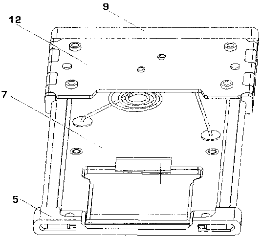
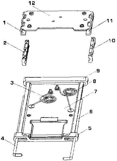
[0009] refer to figure 1 and figure 2 , to provide a sliding mechanism applied to mobile phones, including a sliding seat 7 in a plate-like structure, a sliding plate 12 sleeved on the sliding seat 7, the two sides of the sliding plate 12 are respectively bent inward to form two sleeves that can be sleeved on In the left chute 1 and the right chute 11 on both sides of the slide seat, there are two left torsion springs 3 and right torsion springs 8 that drive the slide plate 12 to slide between the slide seat 7 and the slide plate 12, and the left torsion spring 3 One end of the right torsion spring 8 is connected with the slide seat 7, and the oth


PUM


Abstract

The invention discloses a slide device applied to cellphones. The slide device applied to cellphones comprises a plate-shaped sliding seat and a sliding plate, wherein the sliding plate is sleeved on the sliding seat, a left sliding groove and a right sliding groove are formed on the two sides of the sliding seat, the two sides of the sliding plate are bent inwards to sleeve on the left sliding groove and the right sliding groove, a left torsional spring and a right torsional spring are installed between the sliding seat and the sliding plate, and the left torsional spring and the right torsional spring drive the sliding plate to slide. The slide device applied to cellphones has the advantages of being simple in structure, smooth in sliding, and convenient to use.

Description


Claims


Application Information

Patent Timeline
Owner 金红艳
Why Eureka
Try Eureka