Coordinate tracking system, apparatus and method of use

a tracking system and coordinate technology, applied in the field of geometrical measuring technology, can solve the problems of reducing the accuracy of interferometric measurements, so as to achieve the effect of convenient movemen

Inactive Publication Date: 2007-01-18
VERISURF SOFTWARE
View PDF14 Cites 93 Cited by
  • Summary
  • Abstract
  • Description
  • Claims
  • Application Information

AI Technical Summary

Benefits of technology

The technical effect of this invention is to create an easy-to-use and portable measurement device with a reflector that can rotate around its own axis when used on different surfaces or tracks during movement. This allows users to keep track of their movements over time.

Problems solved by technology

The technical problem addressed in this patent is how to improve the stability of a precision optical measurement system used for precise pointing of objects during the process of manufacture.

Method used


Image

  • Coordinate tracking system, apparatus and method of use
  • Coordinate tracking system, apparatus and method of use
  • Coordinate tracking system, apparatus and method of use

Examples


Embodiment Construction

[0028] The above described drawing figures illustrate the described apparatus and its method of use in at least one of its preferred embodiments, which is further defined in detail in the following description. Those having ordinary skill in the art may be able to make alterations and modifications from what is described herein without departing from its spirit and scope. Therefore, it must be understood that what is illustrated is set forth only for the purposes of example and that it should not be taken as a limitation in the scope of the present apparatus and method of use.

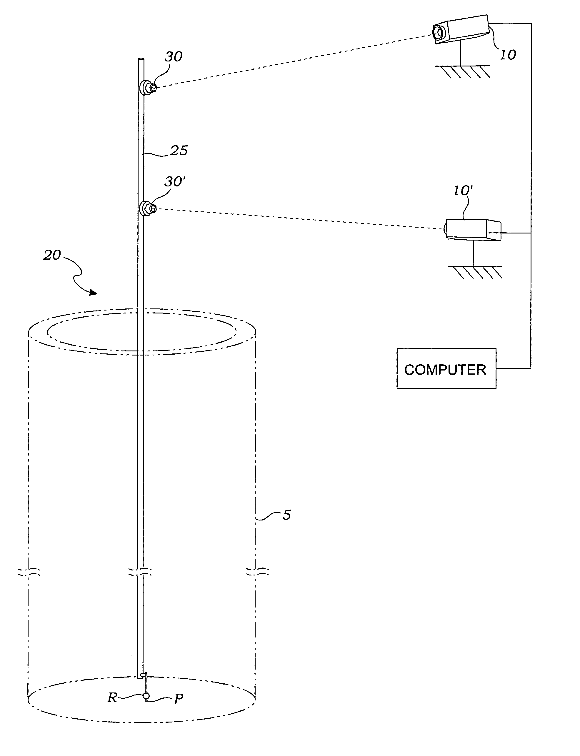
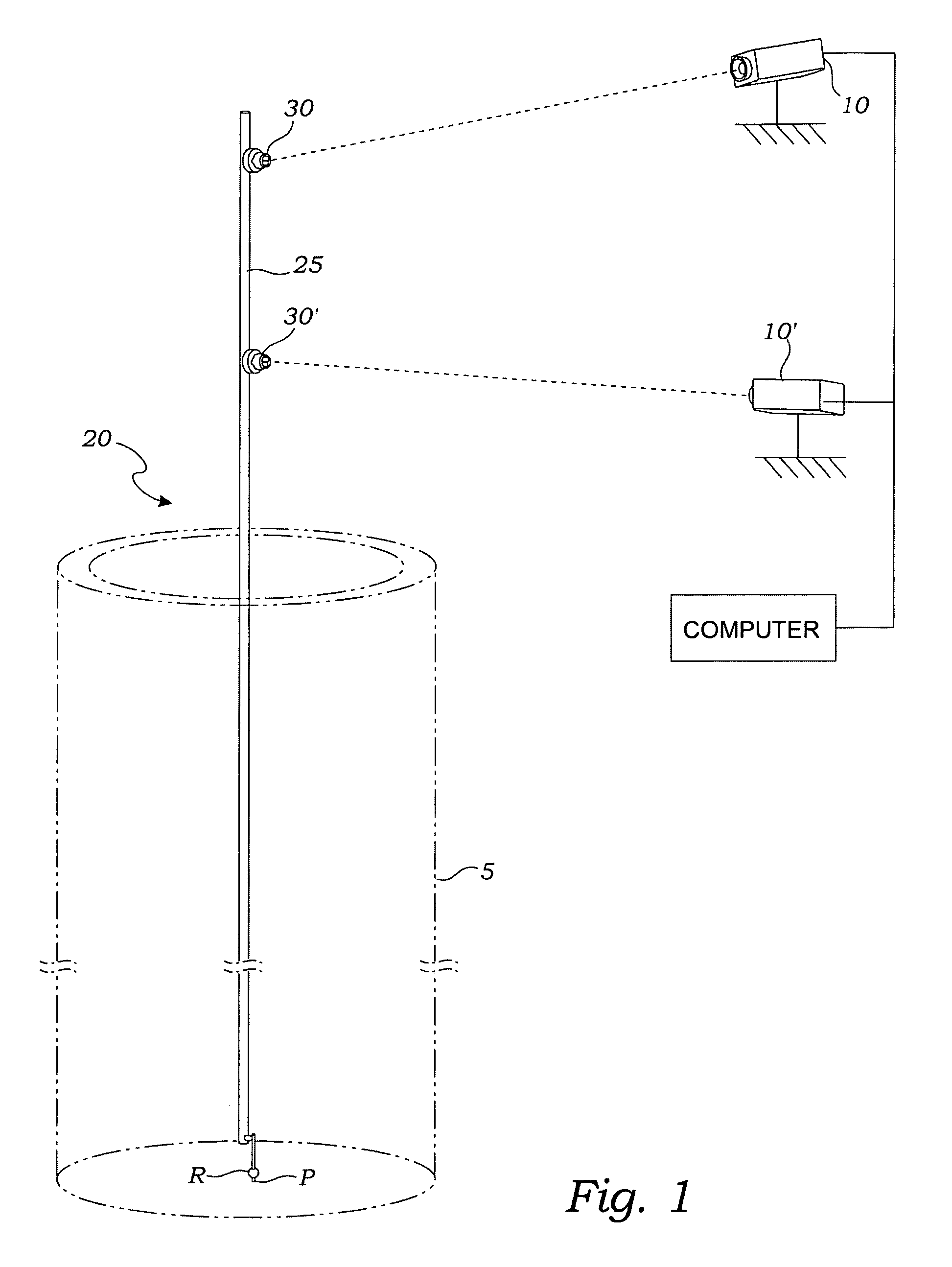
[0029]FIG. 1 illustrates an installation for determining in an indirect manner the position of a point P using, the instant system which comprises two fixed trackers (10 and 10′) wherein the absolute positions of the trackers is known and they are fixed in position as shown. A movable measuring device (20) includes a rigid rod (25); a pair of reflectors (30 and 30′) mounted at fixed positions on the rod (25), and


PUM


Abstract

A system enables indirect determination of a position vector (VR) of a point position (P). The system uses two fixed trackers (10 and 10′) whose absolute positions are known. A movable measuring device (20) provides a rigid rod (25) supporting a pair of reflectors (30 and 30′) which are mounted at fixed positions. A reference point (R) is mounted at a further fixed position on the rod (25) and is on a straight line (L) through the reflectors (30 and 30′). Light beams from the trackers (10 and 10′) acquire the reflectors (30 and 30′) so that when the reference point (R) is positioned at the point position (P), the position vector (VR) of point position (P) is determinate by vector addition.

Description


Claims


Application Information

Patent Timeline
Owner VERISURF SOFTWARE
Why Eureka
Try Eureka