Session relay apparatus and relaying method
a relay and relaying technology, applied in the field of session relay apparatus and session relaying method, can solve the problems of low throughput, difficult fast relay processing, and communication throughput degrade between the transmission terminal and the reception terminal, so as to improve the degraded throughput, high speed, and high speed
- Summary
- Abstract
- Description
- Claims
- Application Information
AI Technical Summary
Benefits of technology
Problems solved by technology
Method used
Image

Examples
first embodiment
(First Embodiment)
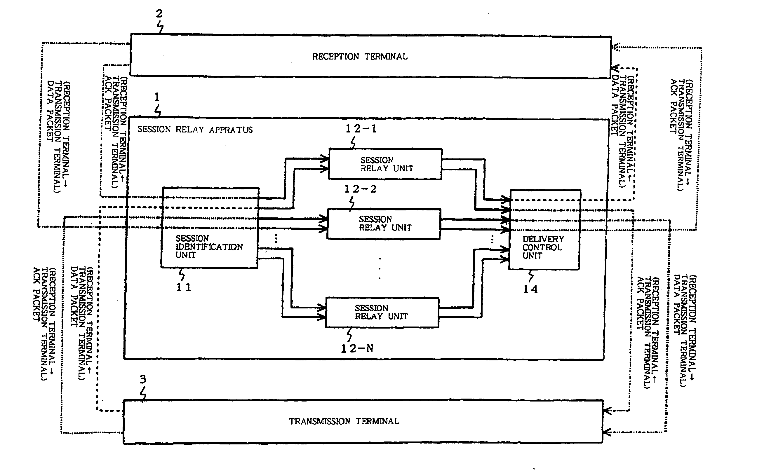
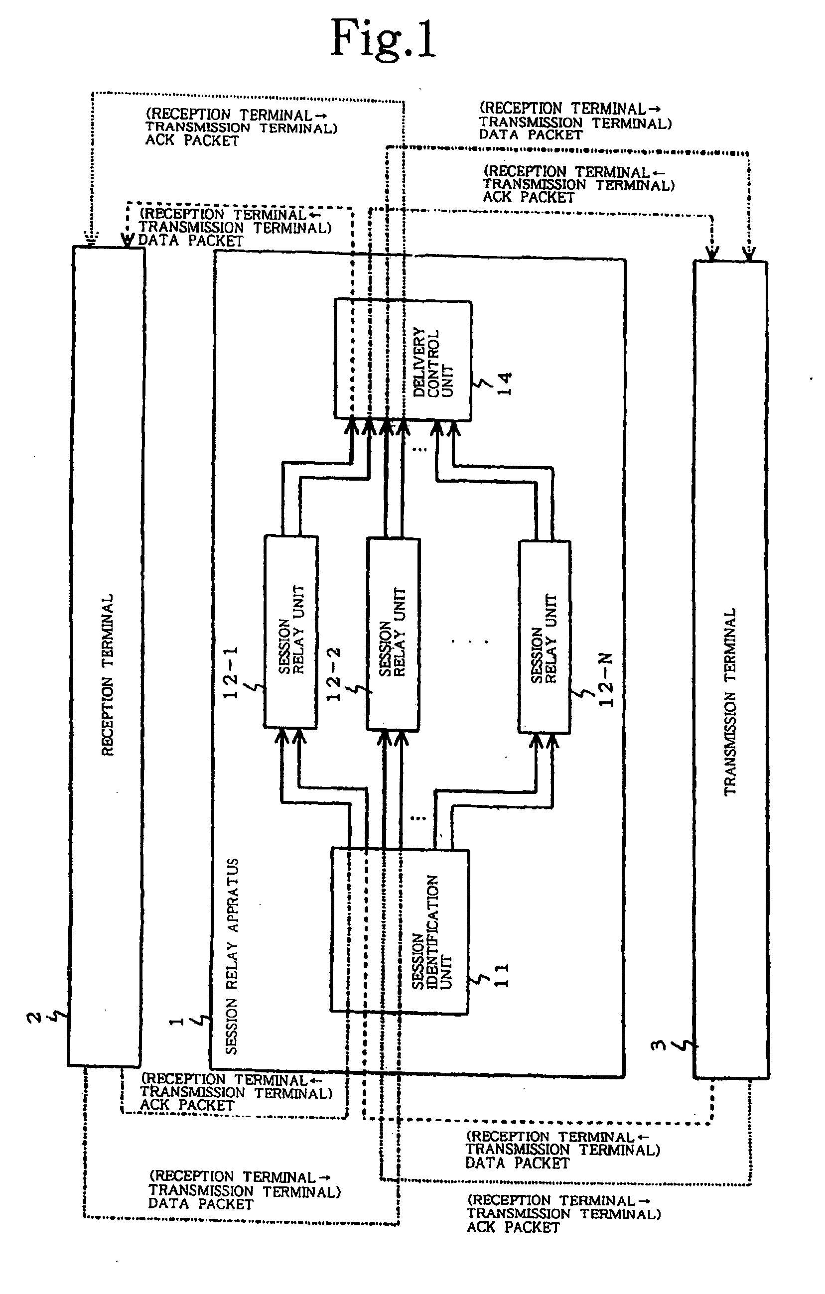
[0057]FIG. 1 is a block diagram illustrating the configuration of a transmission system which includes session relay apparatus 1 according to a first embodiment of the present invention. In FIG. 1, session relay apparatus 1 according to this embodiment comprises session identification unit 11, session relay units 12-1-12-N, and delivery control unit 14, and is connected to reception terminal 2 and transmission terminal 3.
[0058] First, when data is sent from transmission terminal 3 to reception terminal 2, a data packet from transmission terminal 3 is processed by a reception session processing unit (not shown) of session relay unit 12-1, and as a result, an ACK (acknowledgement) packet is returned to transmission terminal 3.
[0059] Data received by the reception session processing unit of session relay unit 12-1 is sent to a transmission session processing unit (not shown) of session relay unit 12-1, and a data packet is transmitted from here to reception terminal 2.
second embodiment
(Second Embodiment)
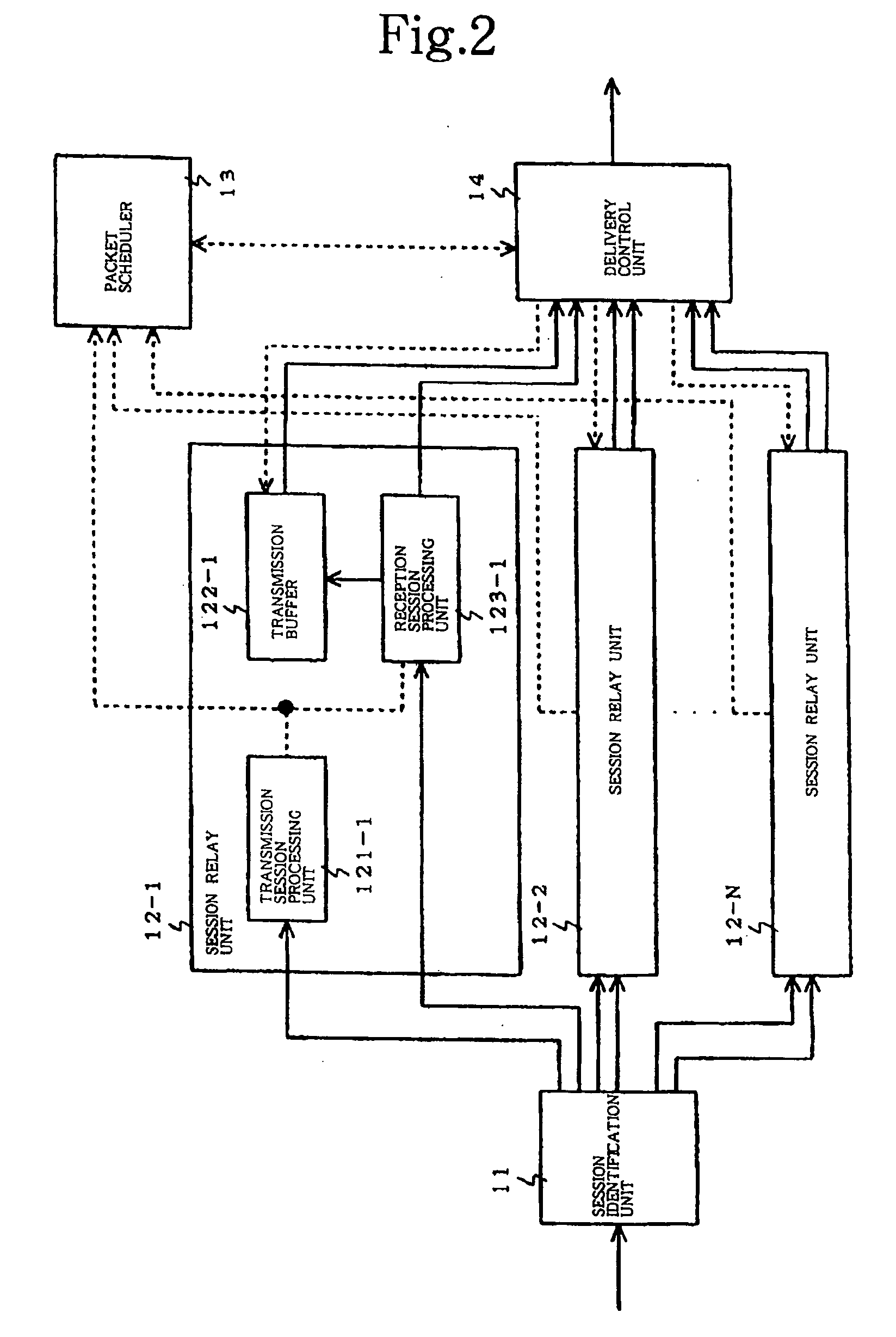
[0100] The configuration of a session relay apparatus according to a second embodiment of the present invention is similar to the configuration of session relay apparatus 1 according to the first embodiment of the present invention illustrated in FIG. 2.
[0101]FIG. 8 is a block diagram illustrating the configuration of a packet scheduler according to the second embodiment of the present invention. In FIG. 8, packet scheduler 16 according to the second embodiment of the present invention is similar in configuration to the first embodiment of the present invention illustrated in FIG. 3 except for the addition of assignment weight changing unit 161 and control parameter changing unit 162, and the same components are designated the same reference numerals. Also, the operation of the same components is similar to the first embodiment of the present invention.
[0102] The operation of packet scheduler 16 according to the second embodiment of the present invention will be de
third embodiment
(Third Embodiment)
[0110]FIG. 9 is a block diagram illustrating the configuration of a session relay apparatus according to a third embodiment of the present invention. In FIG. 9, the session relay apparatus according to the third embodiment of the present invention is similar in configuration to the session relay apparatus according to the first embodiment of the present invention illustrated in FIG. 1, except that reception rate control units 151-1-151-N (reception rate control units 151-2-151-N are not shown) are provided in session relay units 15-1-15-N, and the same components are designated the same reference numerals. Also, the operation of the same components is similar to the first embodiment of the present invention. Reception rate control units 151-1-151-N controls a reception rate from transmission terminal 3.
[0111] While the operation of the session relay apparatus according to the third embodiment of the present invention will be described with reference to FIG. 9, descri
PUM
 Abstract
Description
Claims
Application Information
 - R&D Engineer
- R&D Manager
- IP Professional
- Industry Leading Data Capabilities
- Powerful AI technology
- Patent DNA Extraction
Browse by: Latest US Patents, China's latest patents, Technical Efficacy Thesaurus, Application Domain, Technology Topic.
© 2024 PatSnap. All rights reserved.Legal|Privacy policy|Modern Slavery Act Transparency Statement|Sitemap