Biochemical processing apparatus provided with liquid transport mechanism

a technology of liquid transport mechanism and biochemical processing equipment, which is applied in the direction of chemistry apparatus and processes, instruments, measurement devices, etc., can solve the problems of increasing the number of pipette chips to be discarded, and achieve the effect of reducing the number of pipette chips

Inactive Publication Date: 2007-04-05
CANON KK
View PDF8 Cites 6 Cited by
  • Summary
  • Abstract
  • Description
  • Claims
  • Application Information

AI Technical Summary

Benefits of technology

The technical effect of this patented invention is that it allows for more efficient use of biochip technology by providing an equipment with fewer pipettes than what was previously needed.

Problems solved by technology

This patent describes a technical problem addressed in this patent text relating to the handling of liquids during genetic tests involving DNA microarrays. Specifically, it highlighted concerns about accurate liquid volumes, contamination, and multiple process steps required at once, making it difficult to achieve high efficiency in large numbers of samples. Therefore, the solution presented involves developing a more efficient and effective method for carrying out these processes.

Method used


Image

  • Biochemical processing apparatus provided with liquid transport mechanism
  • Biochemical processing apparatus provided with liquid transport mechanism
  • Biochemical processing apparatus provided with liquid transport mechanism

Examples


Embodiment Construction

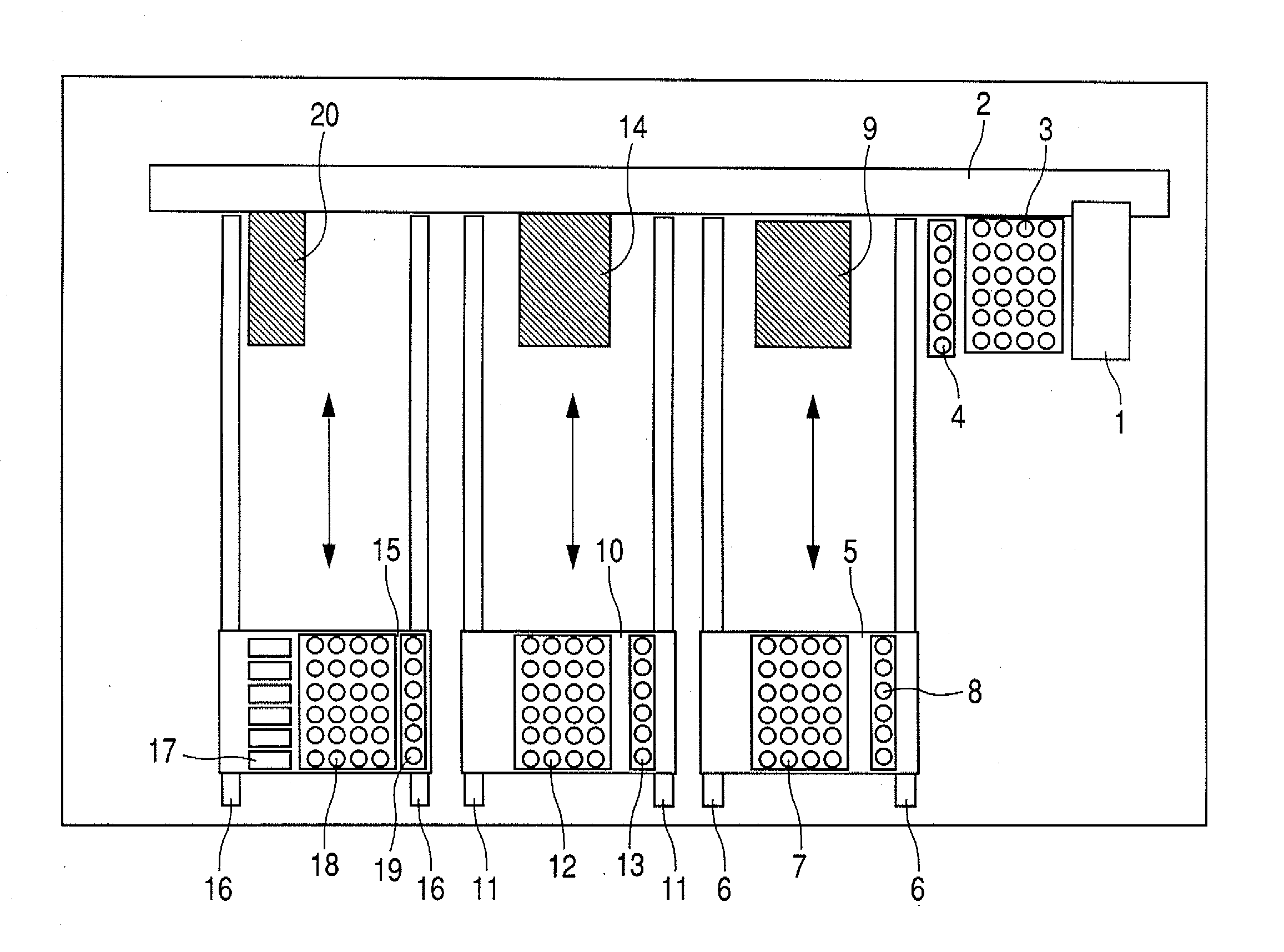
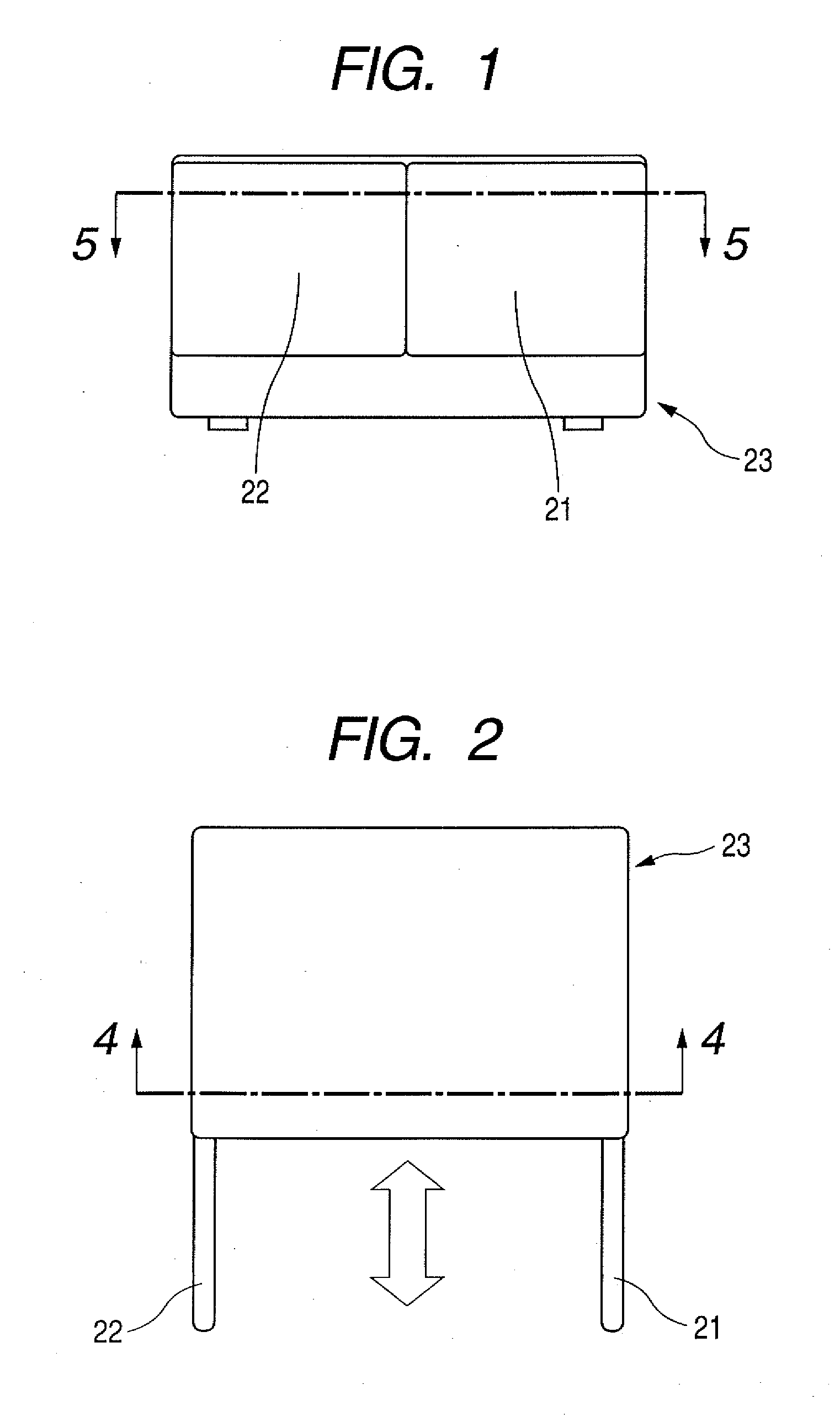
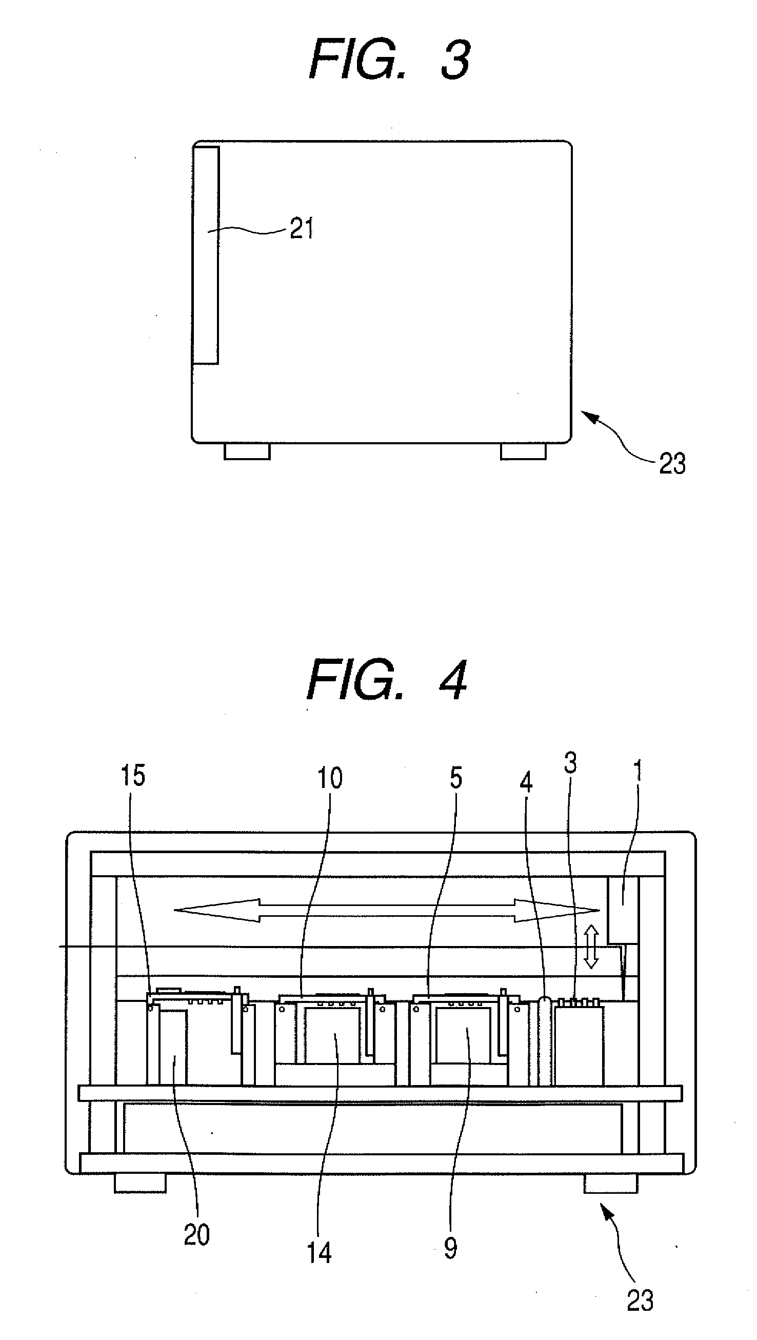
[0019]FIG. 1 is a front view of a biochemical processing apparatus in accordance with an embodiment of the present invention. Here, this embodiment will be described exemplifying a nucleic acid sample testing apparatus. Both a right door 21 and a left door 22 provided on the front of the nucleic acid sample testing apparatus 23 are opened and a well plate or the like is then placed on an installation site in the apparatus. FIG. 2 is a first top view of the nucleic acid sample testing apparatus of the present invention. In the figure, the right and left doors 21 and 22 are being opened.FIG. 3 is a right side view of the nucleic acid sample testing apparatus of the present invention. FIG. 4 is a cross-sectional view of the nucleic acid sample testing apparatus taken along the dashed line 4-4 of FIG. 2. FIG. 5 is a cross-sectional view of the nucleic acid sample testing apparatus taken along the dashed line 5-5 of FIG. 1.

[0020] A pipette 1 for handling a liquid such as a sample or a reag


PUM


Abstract

A biochemical processing apparatus includes a plurality of reaction areas of different types, a pipette for dispensing a liquid, a pipette chip removably attachable on the pipette, and pipette chip storage spaces each capable of holding the pipette chip. The pipette chip storage spaces are provided in the plurality of reaction areas.

Description


Claims


Application Information

Patent Timeline
Owner CANON KK
Why Eureka
Try Eureka