Image processing apparatus, image forming apparatus and related control method
a technology of image processing and forming apparatus, which is applied in the direction of digital output to print units, instruments, visual presentations, etc., can solve the problems of important information leakage and limited reproduction capability of a copying machin
- Summary
- Abstract
- Description
- Claims
- Application Information
AI Technical Summary
Benefits of technology
Problems solved by technology
Method used
Image

Examples
first exemplary embodiment
[0052] First Exemplary Embodiment
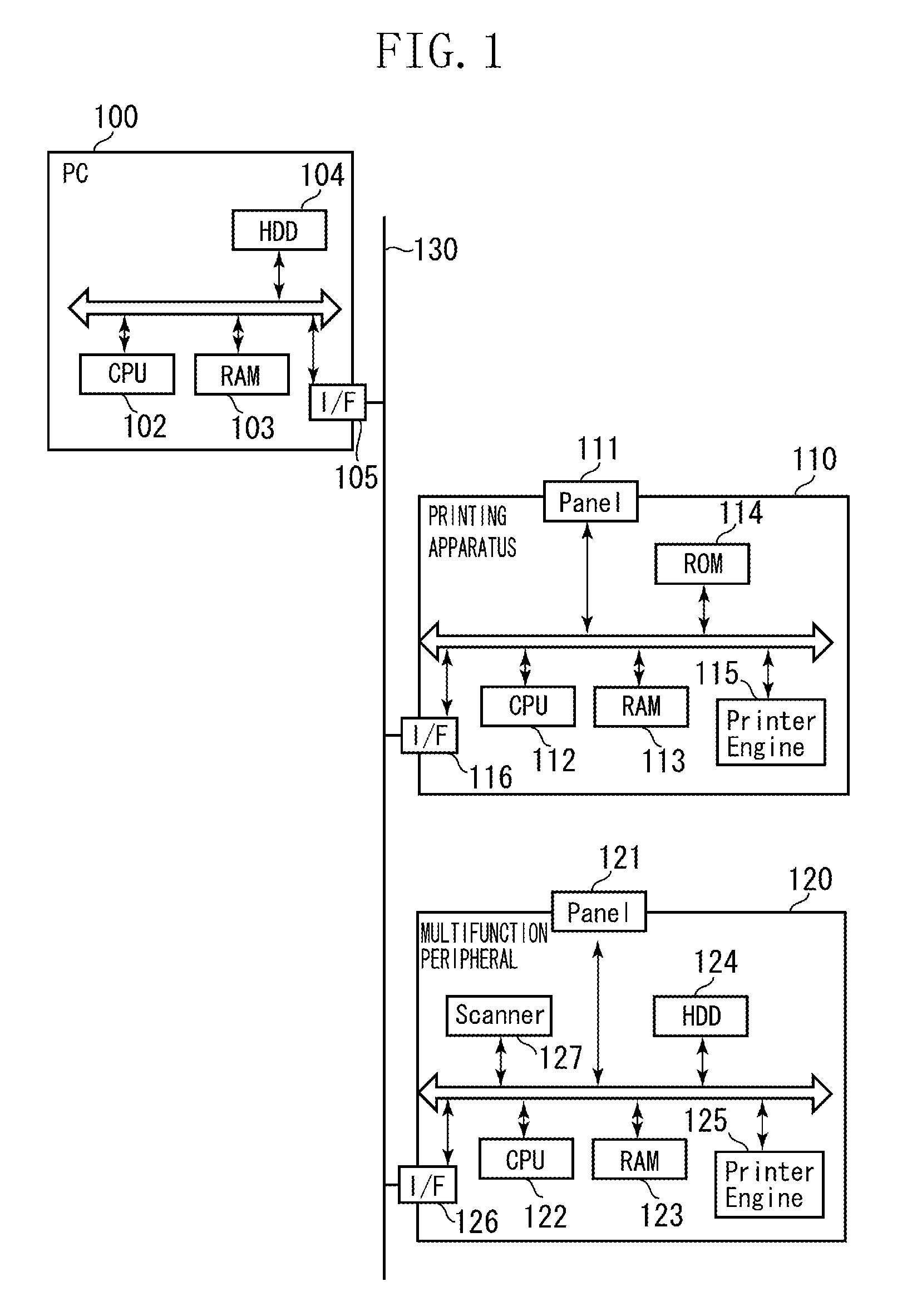
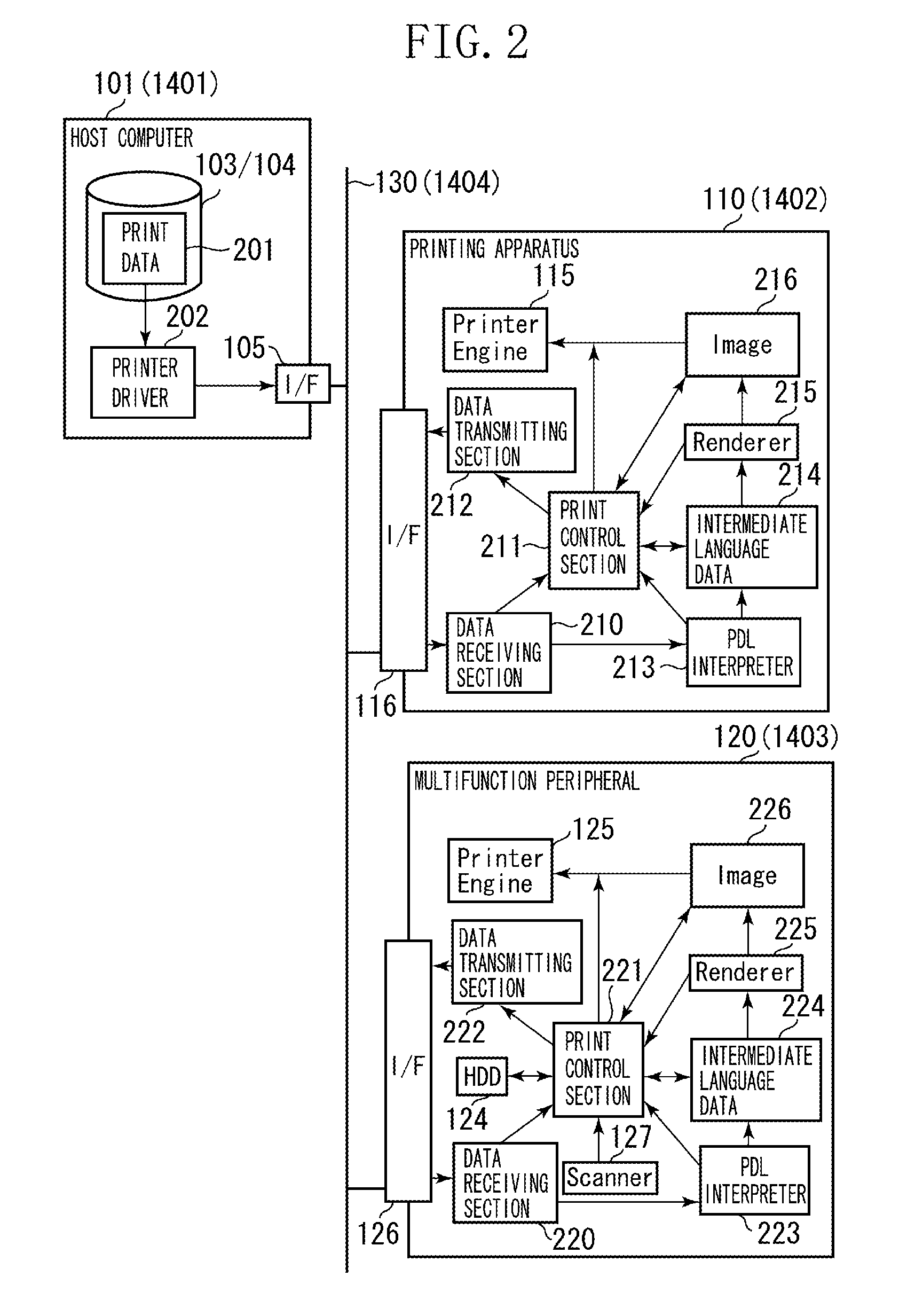
[0053]FIG. 1 is a schematic block diagram illustrating an arrangement of a printing system that can read image data of a scanned document from a storage device and can print an image on a recording paper. As shown in FIG. 1, the printing system includes a host computer 100, a printing apparatus (i.e., a printer) 110, and a multifunction peripheral 120 which are mutually connected via a network 130 (e.g., LAN).
[0054] The host computer 100 includes a CPU 102, a RAM 103, and a hard disk (HDD) 104. The CPU 102 can control various processing performed in the host computer 100. The RAM 103 can be used as a work area of the CPU 102 or a data storage portion. The HDD 104 can store software. A communication interface 105 can control data transmission / reception between the host computer 100 and other apparatus performed via the network 130.
[0055] The printing apparatus 110 includes a panel 111, a CPU 112, a RAM 113, a ROM 114, a printer engine 115, and a comm
second exemplary embodiment
[0147] Second Exemplary Embodiment
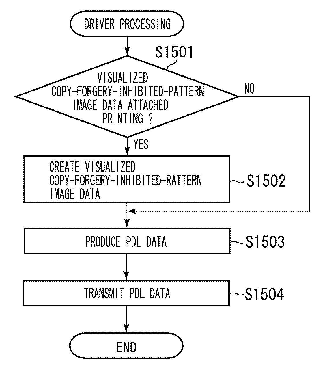
[0148] According to the above-described first exemplary embodiment, a paper document containing identification (ID) is created by the PDL processing. And, a visualized cfip image is attached on a copy product obtainable by copying the paper document.
[0149] The second exemplary embodiment is different from the first exemplary embodiment in that both a cfip image and identification (ID) are added on a paper document created by the PDL processing. Similar to the first exemplary embodiment, a visualized cfip image is added on a copy product obtainable by copying the paper document.
[0150] Thus, the second exemplary embodiment is characterized in that a cfip image is attached on an original while a visualized cfip image (different from the cfip image) is attached on a copy product. In other words, the second exemplary embodiment can discriminate a genuine (i.e., original) based on a cfip image attached thereon. Furthermore, the second exemplary embodiment
third exemplary embodiment
[0179] Third Exemplary Embodiment
[0180] According to the above-described second exemplary embodiment, a paper document containing a cfip image and identification (ID) can be created by the PDL processing. And, a visualized cfip image is added to a copy product obtainable by copying the paper document.
[0181] The third exemplary embodiment is similar to the second exemplary embodiment in that a paper document containing a cfip image and identification (ID) can be created by the PDL processing. However, the third exemplary embodiment is differentiated in that (1) a visualized cfip image or (2) a cfip image is selectively added to a copy product obtainable when the paper document is copied.
[0182] More specifically, when a user instructing execution of the copy processing is identical to a user instructing execution of the PDL processing, a cfip image is added to the copy product. In this manner, the third exemplary embodiment allows a creator of the original to produce a copy product ide
PUM
 Abstract
Description
Claims
Application Information
 - R&D Engineer
- R&D Manager
- IP Professional
- Industry Leading Data Capabilities
- Powerful AI technology
- Patent DNA Extraction
Browse by: Latest US Patents, China's latest patents, Technical Efficacy Thesaurus, Application Domain, Technology Topic.
© 2024 PatSnap. All rights reserved.Legal|Privacy policy|Modern Slavery Act Transparency Statement|Sitemap