Method and apparatus for heat treating a fuel assembly channel made of a zirconium alloy

a technology of fuel assembly channel and zirconium alloy, which is applied in the direction of lighting and heating apparatus, furnace types, reactor fuel elements, etc., can solve the problems of different material parameters of corner regions and wall regions, and achieve the effects of less power, increased inductive coupling, and greater variability

Inactive Publication Date: 2007-06-14
AREVA GMBH
View PDF7 Cites 1 Cited by
  • Summary
  • Abstract
  • Description
  • Claims
  • Application Information

AI Technical Summary

Benefits of technology

Inventions described earlier involve two steps: 1. Using multiple electrical conductors or wires called primary and secondary windings on both sides of a core made from magnetically permeable metal plate (M) covered by insulating layers like glass fiber cloth). These electric conductor arrangements creates loops where current flows when they're excited at certain frequencies. By controlling how much energy passes into these loop areas based upon their position relative to other parts of the M grid structure, the system allows precise and repeatable changes in voltage applied across each area. Additionally, due to the reduced size of the cores involved, which further increases the efficiency of induced heat generation. Overall, this technology improves the performance of nuclear reactors while reducing costs associated with maintenance work.

Problems solved by technology

The technical problem addressed in this patented technology relates to improving the efficiency or effectiveness of an electronic device by optimizing its performance based on factors like temperature and humidity levels that affect their operation.

Method used


Image

  • Method and apparatus for heat treating a fuel assembly channel made of a zirconium alloy
  • Method and apparatus for heat treating a fuel assembly channel made of a zirconium alloy
  • Method and apparatus for heat treating a fuel assembly channel made of a zirconium alloy

Examples


Embodiment Construction

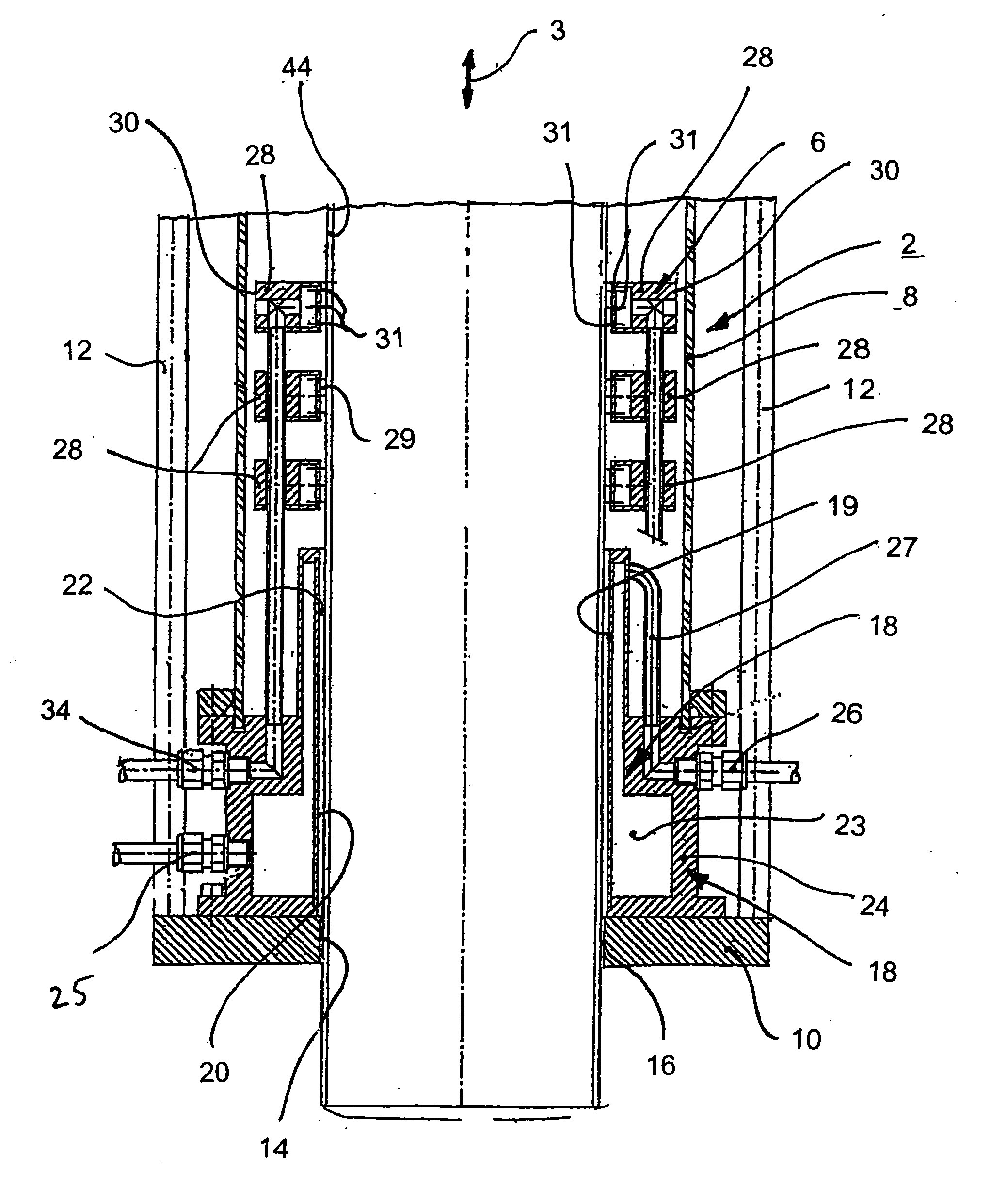
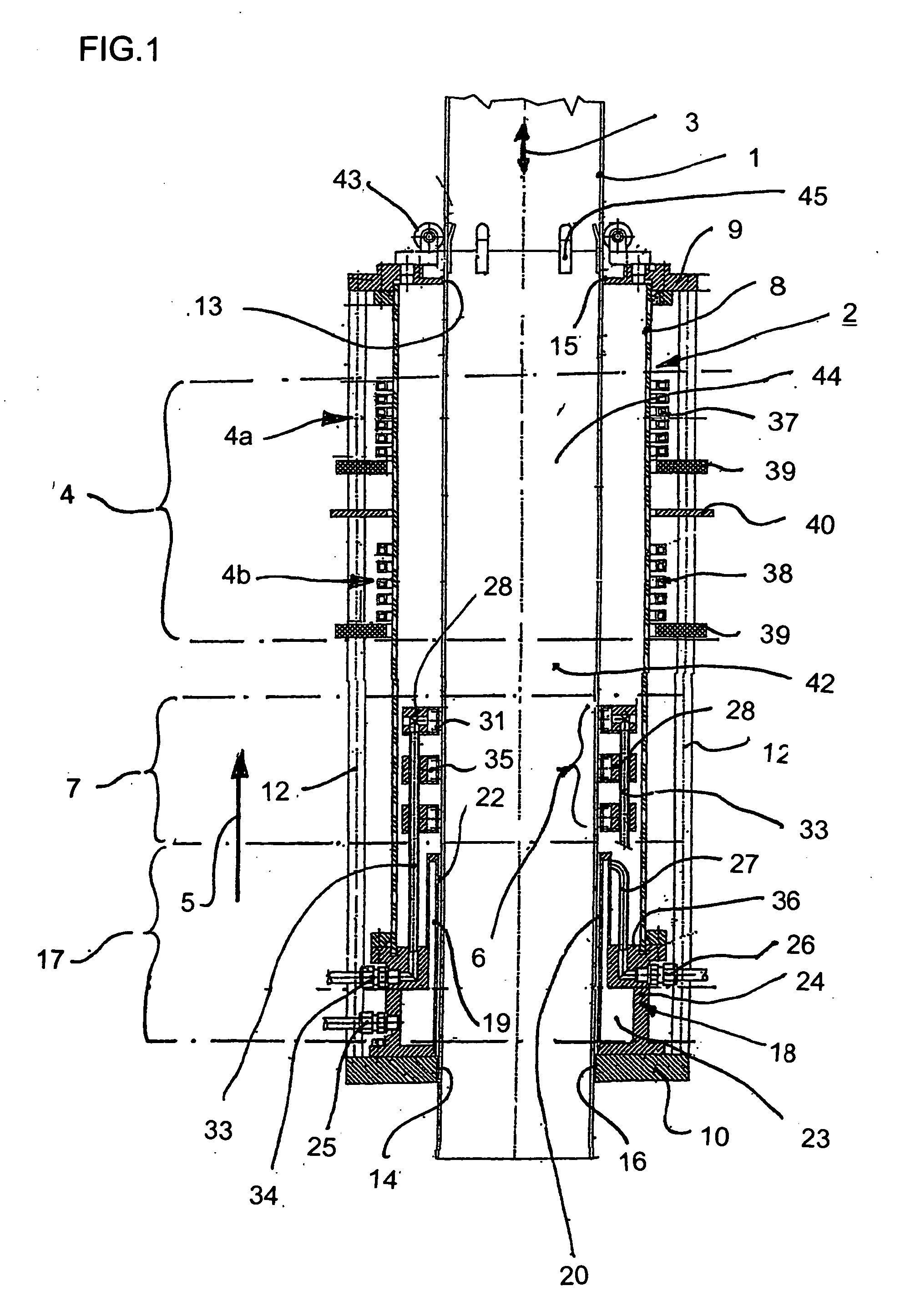
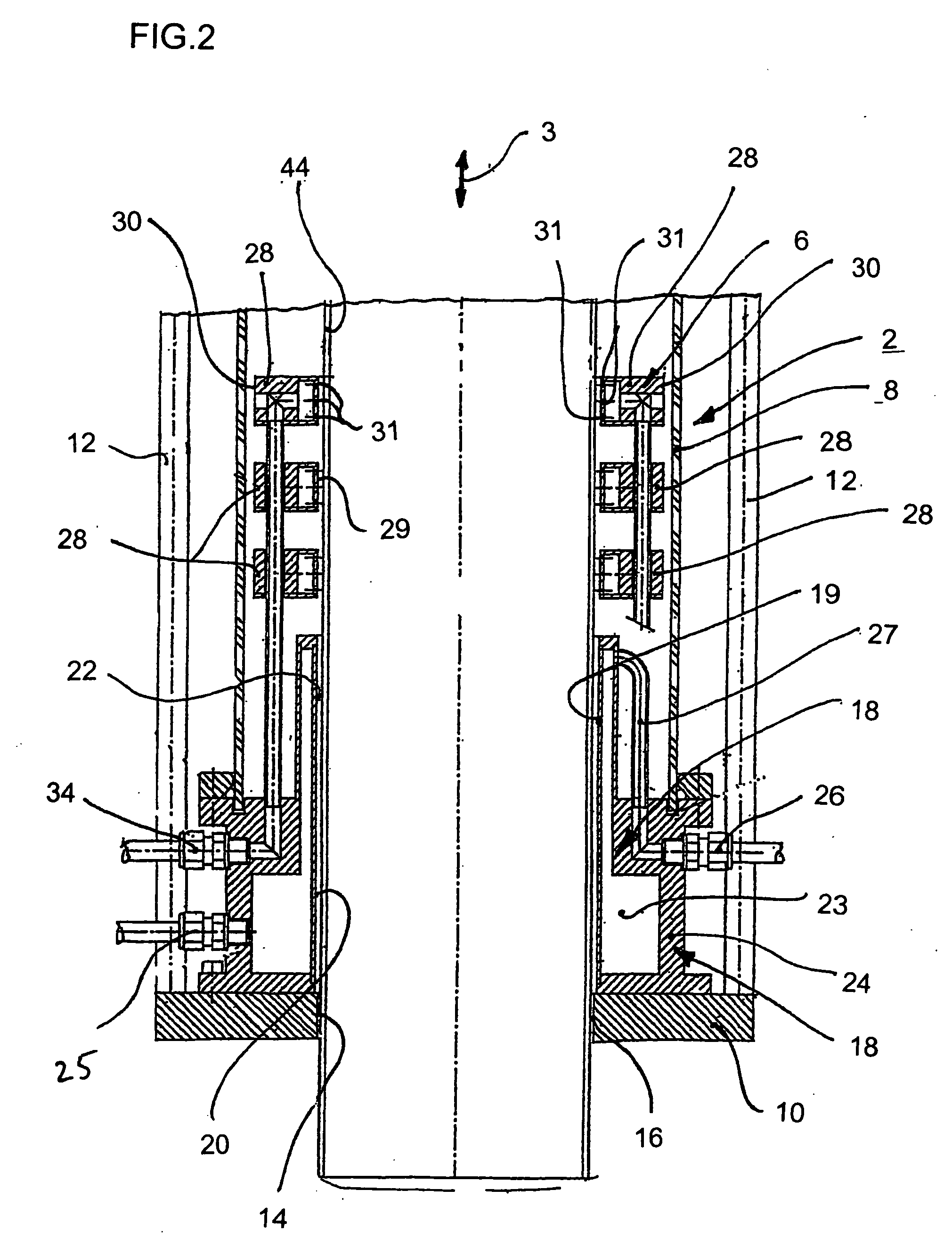
[0025] Referring now to the figures of the drawing in detail and first, particularly, to FIGS. 1-4 thereof, there is shown an apparatus for heat treating a fuel assembly channel or box 1. The apparatus contains a housing 2, which is carried vertically, or in a longitudinal direction 3 of the channel, on a non-illustrated frame, a heating zone 4 having a first heating device 4a and a second heating device 4b and a nozzle configuration 6 forming a first cooling zone 7. The housing 2 contains a cylinder made of glass, that is to say of a material permeable to electromagnetic fields. The housing 2 furthermore contains an upper flange 9 and a lower flange 10, both flanges 9, 10 being approximately in the form of a circular disk and being linked via bars 12, which are disposed coaxially outside a cylinder 8. The flanges 9, 10 have in each case a central opening 13 and 14 respectively. The shape of the openings 13, 14 complements the contour of the fuel assembly channel 1, which passes throug


PUM

PropertyMeasurementUnit
Timeaaaaaaaaaa
Temperatureaaaaaaaaaa
Electrical conductivityaaaaaaaaaa

Abstract

In a method for heat treating a fuel assembly channel made of zircaloy, the channel is continuously moved relative to a heat-treatment device and, longitudinal sections of it are heated to the beta phase range in an inductive heating zone. The longitudinal section of the channel heated in this manner is than cooled in a cooling zone to a temperature within an alpha phase range. The heat treatment is effected by at least two heating devices, which are spaced apart from one another, operate independently of each other, and each contain at least one induction coil and together form a heating zone. The channel section is first heated using a first heating device and then heat-treated using a second heating device which has less power and in that cooling is effected using a stream of inert gas applied to the outer surface of the channel.

Description


Claims


Application Information

Patent Timeline
Owner AREVA GMBH
Why Eureka
Try Eureka