Hydraulic control apparatus of working machine

Active Publication Date: 2007-09-06
KOBELCO CONSTR MASCH CO LTD
View PDF1 Cites 6 Cited by
  • Summary
  • Abstract
  • Description
  • Claims
  • Application Information

AI Technical Summary

Benefits of technology

[0019]Accordingly, it is an object of the present invention to provide a hydraulic control apparatus of working machine capable of reducing all problems in driving force shortage due to the cutoff control while improving the energy efficiency with the cutoff control, and further, additional installation of new equipment is not necessary.

Problems solved by technology

Then, a pressure loss due to the throttle occurs, and the desired effect in energy efficiency improvement in the entire system is not enough.
According to Japanese Unexamined Patent Application Publication No. 2002-038536, due to heat capacity of the relief valve, a time lag is generated between a generation of the relief flow rate and a temperature increase of the relief valve, the execution of the cutoff control is delayed.
Accordingly, the reduction effect of the relief loss is not enough.
Accordingly, as long as the pressure feedback control is selected, the pump pressure is not increased to the maximum pressure, and the driving force comes short and result in, for example, decrease in hill-climbing ability on a sloping road.
Accordingly, the instillation cost is increased and the application of the detection means and the wiring equipment on the existing machine is difficult.
Further, the shortage of driving force can occur not only in the hill-climbing but in various operations, however, any countermeasure to this problem has not been taken.
However, the rotation pressure is not increased, and the rotating body can rotate in only a very slow speed or can stop without rotation.
This can occur in rotation on a flat road, and the problem becomes significant in an increasing rotation at the time of rotating to the upper side on a sloping road.

Method used


Image

  • Hydraulic control apparatus of working machine
  • Hydraulic control apparatus of working machine
  • Hydraulic control apparatus of working machine

Examples


Example

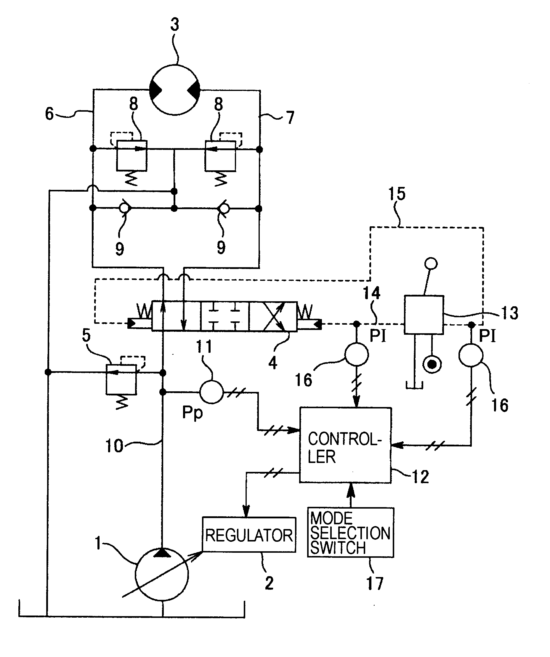
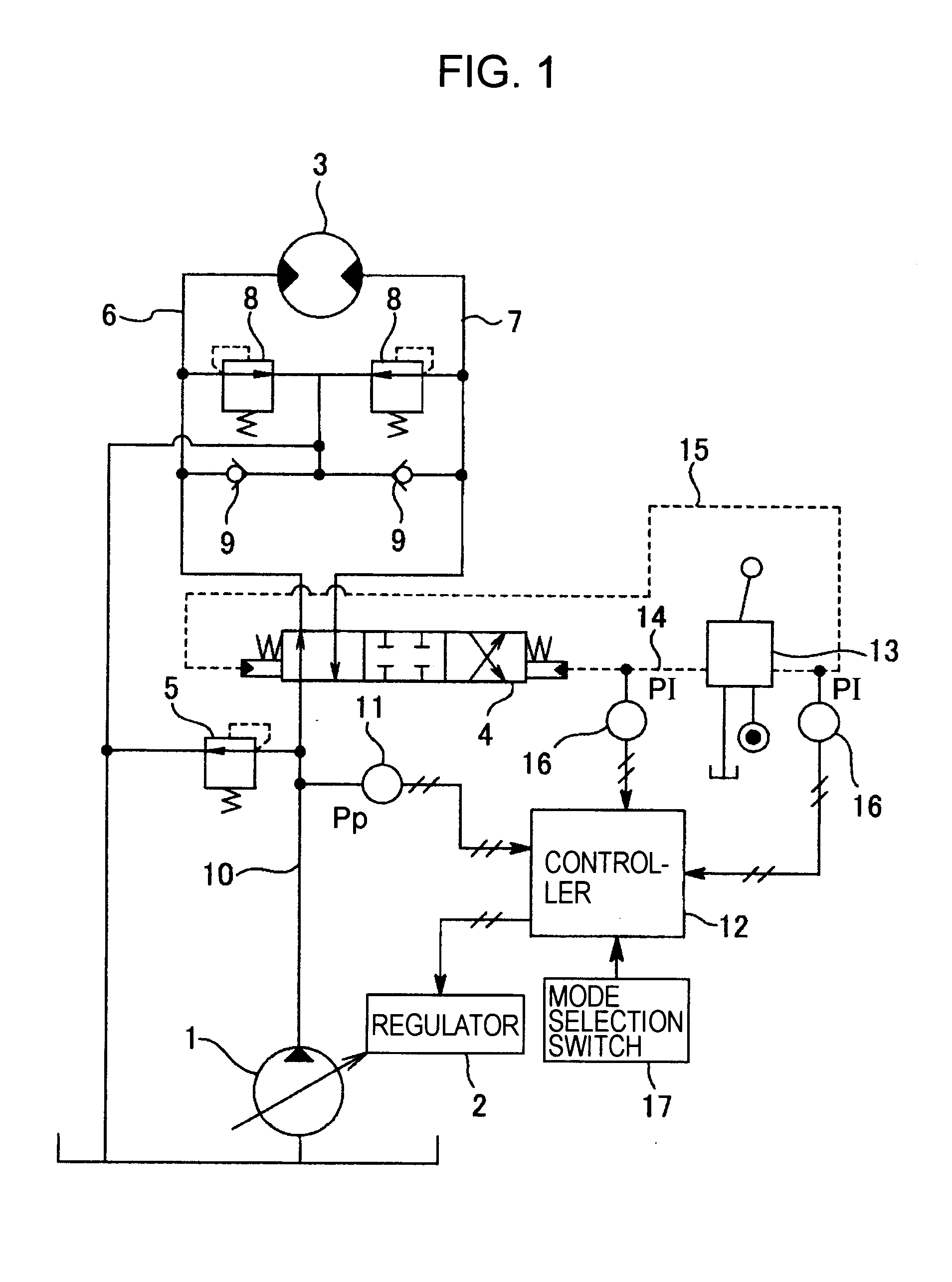
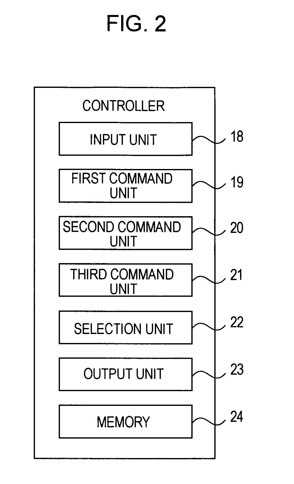
[0052]FIG. 1 is a schematic diagram of a hydraulic circuit of working machine, for example, a hydraulic excavator, according to the embodiment of the present invention, and FIG. 2 is a view illustrating an internal structure of a controller as control means, respectively.

[0053]In FIG. 1, a variable displacement type hydraulic pump 1 is a hydraulic source, a regulator 2 controls a discharge amount (pump flow rate) of the pump 1, a hydraulic motor 3 is an example of hydraulic actuators, a hydraulic pilot type control valve 4 controls supply and discharge of oil with respect to the hydraulic motor 3, and a relief valve 5 sets a maximum pressure of the circuit.

[0054]Between both conduits 6 and 7 which connect the control valve 4 and the hydraulic motor 3, port relief valves 8 and make up check valves 9 are provided. T denotes a tank.

[0055]On a pump line 10 in which pump oil is discharged, a pump pressure sensor 11 is provided. A pump pressure (upstream side pressure of the relief valve 5)


PUM


Abstract

With respect to a method of controlling a pump flow rate of a hydraulic pump, a method having a small flow rate command value is selected between a pressure feedback control for controlling the pump flow rate based on a set pressure (a cutoff pressure) and a pump pressure, and, an ordinary control for controlling the pump flow rate based on operation information, and in a case that the pressure feedback control is selected, a flow rate increasing control for increasing the flow rate command value after the case with the passage of time is performed.

Description


Claims


Application Information

Patent Timeline
Owner KOBELCO CONSTR MASCH CO LTD
Why Eureka
Try Eureka