Vortex type fluid machine and assembling method thereof

A fluid machinery, scroll technology, applied in the field of scroll compressors, to achieve the effect of improving energy efficiency and high energy efficiency

Active Publication Date: 2011-09-21
HITACHI JOHNSON CONTROLS AIR CONDITIONING INC
View PDF5 Cites 0 Cited by
  • Summary
  • Abstract
  • Description
  • Claims
  • Application Information

AI Technical Summary

Problems solved by technology

Therefore, when the fixed scroll is fixed to the frame, there is a possibility that it may be fixed by rotating or translating the amount of the clearance from the neutral position which is the theoretical meshing position.

Method used


Image

  • Vortex type fluid machine and assembling method thereof
  • Vortex type fluid machine and assembling method thereof
  • Vortex type fluid machine and assembling method thereof

Examples


Embodiment 1

[0035] use Figure 1 to Figure 7 Example 1 of the present invention will be described.

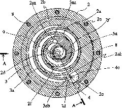
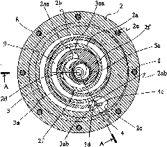
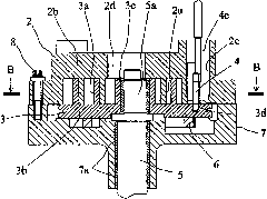
[0036] figure 1 It is a top sectional view showing a shaft-penetrating scroll compressor of a scroll fluid machine according to this embodiment, and is the same as figure 2 The equivalent diagram of the B-B profile. figure 2 yes figure 1 The longitudinal section view, is with figure 1 The A-A profile is comparable to the figure.

[0037]In these figures, the compression mechanism unit 1 is composed of a frame body 7, a fixed scroll 2 attached to the frame body 7, an orbiting scroll 3 engaged therewith, and the like. In a hermetic compressor, the frame body 7 is generally fixed to an airtight container (not shown), and the fixed scroll 2 is fixed by fixing bolts 8 passing through a plurality of holes 2e provided on its outer periphery. on the frame 7.

[0038] The fixed scroll 2 is provided with a mirror plate 2b, a spiral coil 2a erected on the mirror plate 2b, a suction port 2c a...

Embodiment 2

[0053] Next, use Figure 8 ~ Figure 10 Example 2 of the present invention will be described. This embodiment shows an example in which the present invention is applied to a scroll fluid machine having a structure in which the crankshaft does not penetrate the orbiting scroll member. In these figures, the parts given the same symbols as those in Example 1 represent the same or corresponding parts. In this embodiment, the orbiting scroll 3 is vertically provided with a spiral wrap on one surface side of the mirror plate, and an orbiting bearing 3c for driving the orbiting scroll is provided near the center of the opposite surface (back side). The crank portion of the crankshaft is inserted into the swivel bearing 3c.

[0054] Figure 8 is equivalent to Example 1 Figure 5 diagram, with Figure 5 In the same manner as in the above case, the outline of the wrap 2a of the fixed scroll 2 is superimposed on the orbiting scroll 3 with a one-dot dash line so that the center Om of ...

Embodiment 3

[0058] Next, use Figure 11 and Figure 12 Embodiment 3 of the present invention will be described. In these figures, the parts given the same symbols as those of the above-mentioned Example 1 and Example 2 represent the same or corresponding parts. Figure 11 is a top sectional view of the scroll fluid machine of this embodiment, Figure 12 is equivalent to Figure 11 A longitudinal sectional view of the E-E section. In the above-mentioned embodiments 1 and 2, the inflow of the working fluid to the compression mechanism part adopts the longitudinal suction structure in which the working fluid enters the suction port of the fixed scroll from the axial direction, but in this embodiment, the present invention is applied to the fixed scroll. A scroll type fluid machine of a horizontal suction structure in which a suction port 2 c is provided in a direction (radial direction) perpendicular to the axis of the scroll 2 .

[0059] Compared with the vertical suction structure, the ...


PUM


Abstract

The invention discloses a vortex type fluid machine and an assembling method thereof, wherein the device is capable of easily and properly engaging a coil plate of a rotary vortex disc with a coil plate of a fixed vortex disc so as to improve energy efficiency. The vortex type fluid machine comprises the fixed vortex disc (2) and the rotary vortex disc (3), wherein the fixed vortex disc is provided with a vortex-shaped coil plate on a mirror plate; the rotary vortex disc is provided with the vortex-shaped coil plate which is engaged with the coil plate of the fixed vortex disc so as to form a compression chamber, and capable of convolution without auto-rotating. A positioning hole (3d) for mounting a positioning pin (4) in the case of assembling is arranged on a coil plate extension wire near a coil plate extremity coil part (3ab) of the fixed vortex disc; an extremity coil circular arc part (2ab) buckled with the positioning pin in the case of assembling is arranged on the coil plate extremity coil part of the fixed vortex disc; and the centre of the positioning hole and the centre of the circular arc of the extremity coil circular arc part are approximately accordant when being assembled in the case that the centers of the fixed vortex disc and the rotary vortex disc are accordant.

Description

technical field [0001] The invention relates to a scroll fluid machine using refrigerant, air and other compressive fluids, and is especially suitable for a shaft-through scroll compressor. Background technique [0002] Japanese Patent No. 3170111 discloses a conventional example of a shaft-through type scroll compressor as a compressor having a structure in which the crankshaft penetrates the orbiting scroll. The scroll compressor with such a structure has an advantage that no torque that tilts the orbiting scroll is generated because the bearing is located at the position where the gas load that operates on the orbiting scroll acts. Therefore, it is characterized in that the so-called oscillating motion in which the orbiting scroll performs orbiting motion can be suppressed, and the tip clearance of the wrap can be maintained uniformly, thereby reducing internal leakage and achieving high performance. [0003] In addition, in the above-mentioned through-type scroll compre...

Claims


Application Information

Patent Timeline
IPC IPC(8): F04C18/02
CPCF04C18/0215F04C18/0269F04C29/0021F04C2210/26F04C2230/60F04C2240/30Y10S415/00Y10S417/00
Inventor 香曾我部弘胜藤村和幸岛田敦田所哲也村上晃启
Owner HITACHI JOHNSON CONTROLS AIR CONDITIONING INC
Why Eureka
Try Eureka