Substrate holder for optical coating machines

Inactive Publication Date: 2007-10-25
JDS UNIPHASE CORP
View PDF5 Cites 10 Cited by
  • Summary
  • Abstract
  • Description
  • Claims
  • Application Information

AI Technical Summary

Problems solved by technology

The process of mounting the substrates 2 in the openings 5 often cause particulate generation, which, even for particles as small as one micron, can greatly degrade the performance of the laser.
The multi-piece substrate holder 1 also necessitates time consuming assembly steps, and a complicated cleaning process.

Method used


Image

  • Substrate holder for optical coating machines
  • Substrate holder for optical coating machines
  • Substrate holder for optical coating machines

Examples


Example

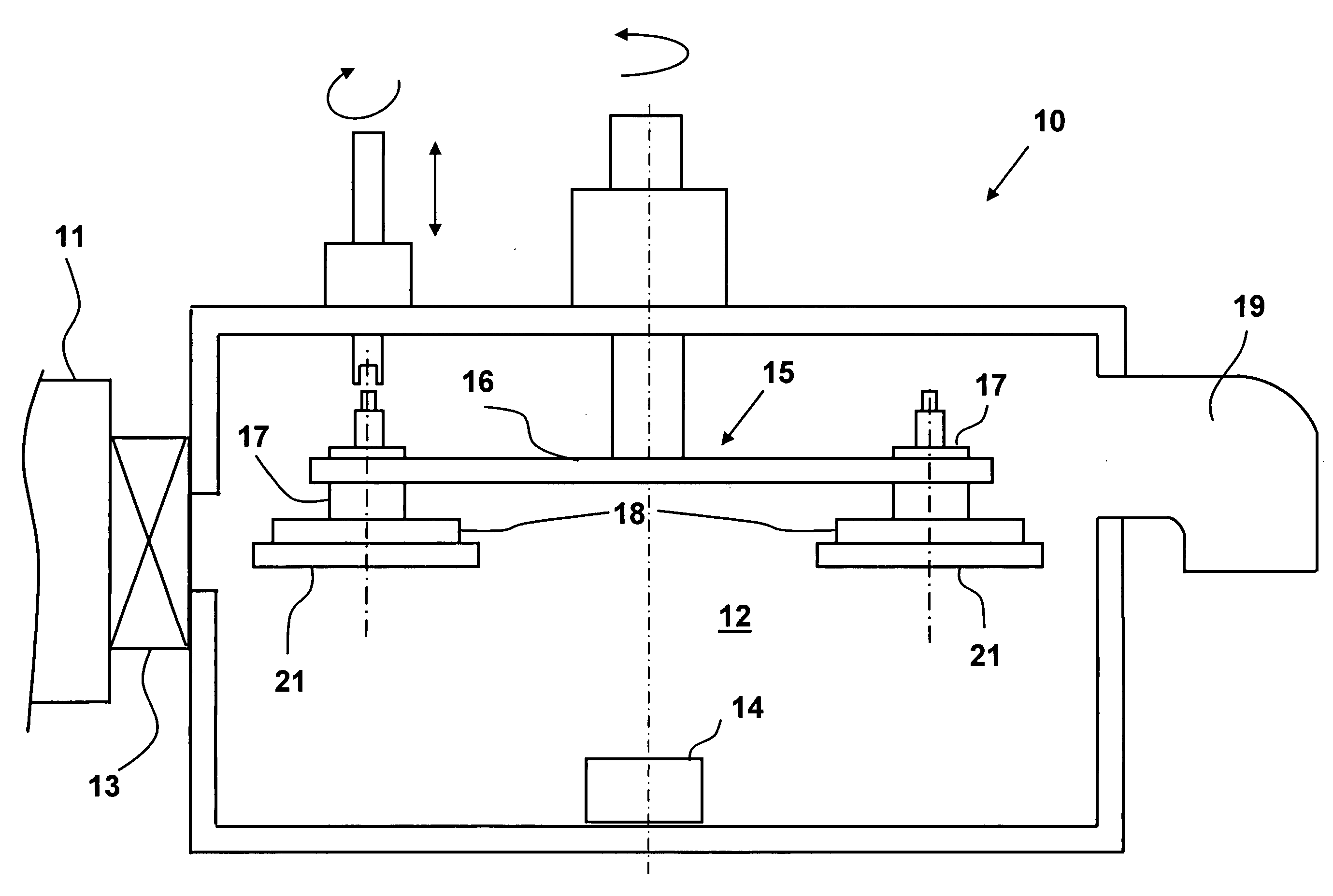
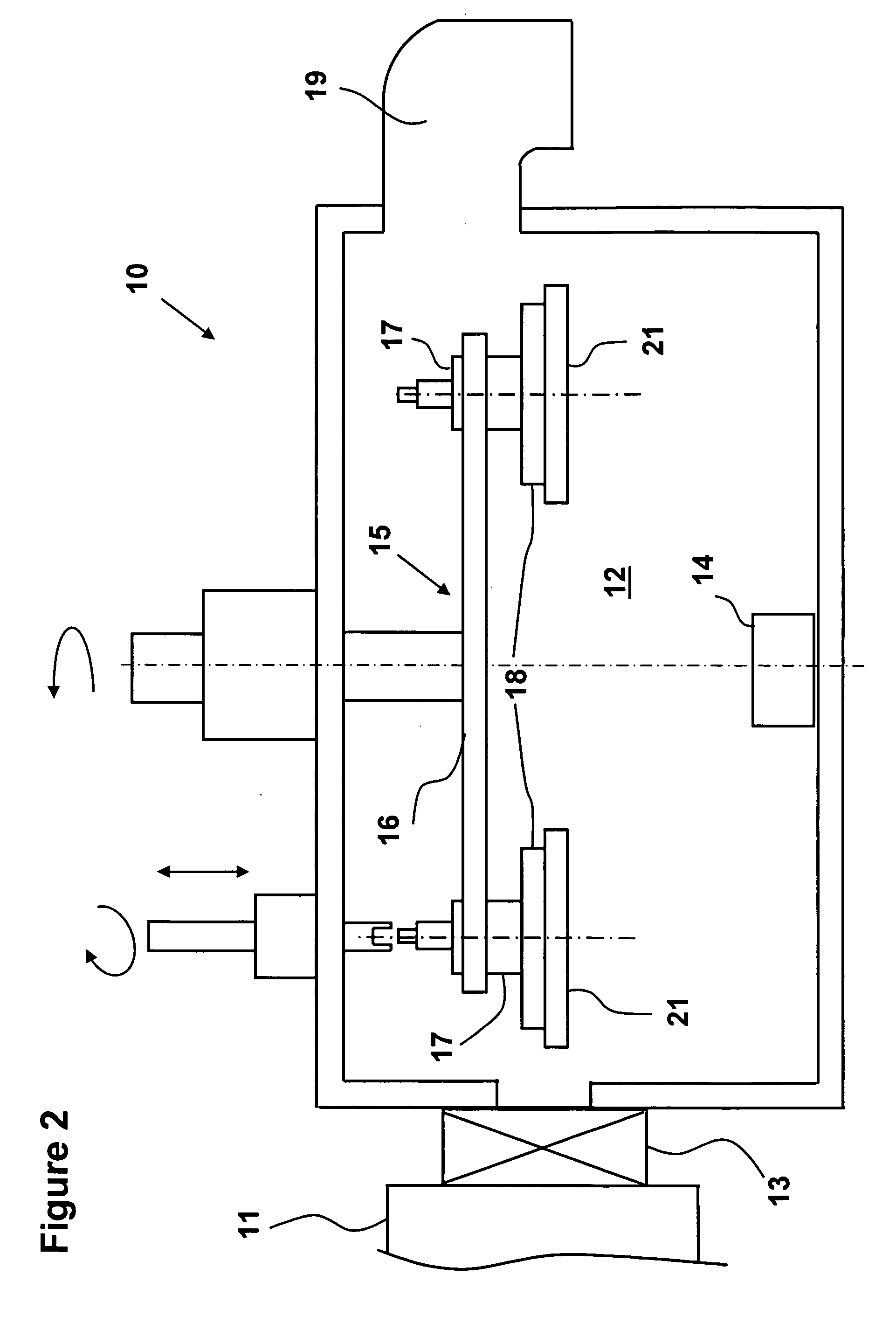
[0015] With reference to FIG. 2, a coating machine 10, e.g. a Physical Vapor Deposition (PVD) or a Chemical Vapor Deposition (CVD) system, for use with the present invention includes a load lock chamber, generally indicated at 11, and a process chamber 12 with a gate valve 13 therebetween. The gate valve 13 enables the pressure in the load lock chamber 11 to be brought to atmospheric pressure for loading and unloading of substrates or to be re-established to the pressure of the process chamber 12 for substrate transfer, independently of the pressure in the process chamber 12. Preferably, the load lock chamber 11 includes a loading container with a cassette elevator therein, and a transfer channel with a robotic arm therein for transferring the substrate holders between the load lock chamber 11 and the process chamber 12.

[0016] A cathode 14, and a planetary substrate support 15 are mounted within the process chamber 2. The planetary substrate support 15 comprises a main cylindrical pla


PUM

PropertyMeasurementUnit
Flexibilityaaaaaaaaaa

Abstract

A substrate holder for supporting substrates during coating processes includes an expandable outer frame, and a plurality of flexible arms defining a mesh or lattice like structure. Openings, formed by the interconnecting flexible arms, are defined by a plurality of resilient walls, which alternatively flex into and out of each opening providing equally spaced points of support for each substrate.

Description


Claims


Application Information

Patent Timeline
Owner JDS UNIPHASE CORP
Why Eureka
Try Eureka