Avoiding temperature-related faults of a laser by temperature adjustment

Inactive Publication Date: 2008-02-14
TORSANA LASER TECH
View PDF8 Cites 24 Cited by
  • Summary
  • Abstract
  • Description
  • Claims
  • Application Information

AI Technical Summary

Benefits of technology

[0010] Accordingly, the invention preferably seeks to mitigate, alleviate or eliminate one or more of the above mentioned disadvantages singly or in any combination. In particular, it may be seen as an object of the present invention to provide a method for min

Problems solved by technology

The stresses may result in misalignment of the laser since the fixation of the optical components relative to the optical mount may be lost or altered.
Thus, temperature variations that cause changes of sizes and shapes of the optical mount may lead to mechanical faults which again lead to optical misalignments and faults of the laser.
However, such beneficial mechanical designs may be expensive and may require special metals and complex mechanical designs.
Accordingly, a problem is to obtain an inexpensive and mechanically simple method for minimising temperature-related faults and misalignments of lasers.
Other effects than temperature-related stresses, as well as combinations of other

Method used


Image

  • Avoiding temperature-related faults of a laser by temperature adjustment
  • Avoiding temperature-related faults of a laser by temperature adjustment
  • Avoiding temperature-related faults of a laser by temperature adjustment

Examples


Embodiment Construction

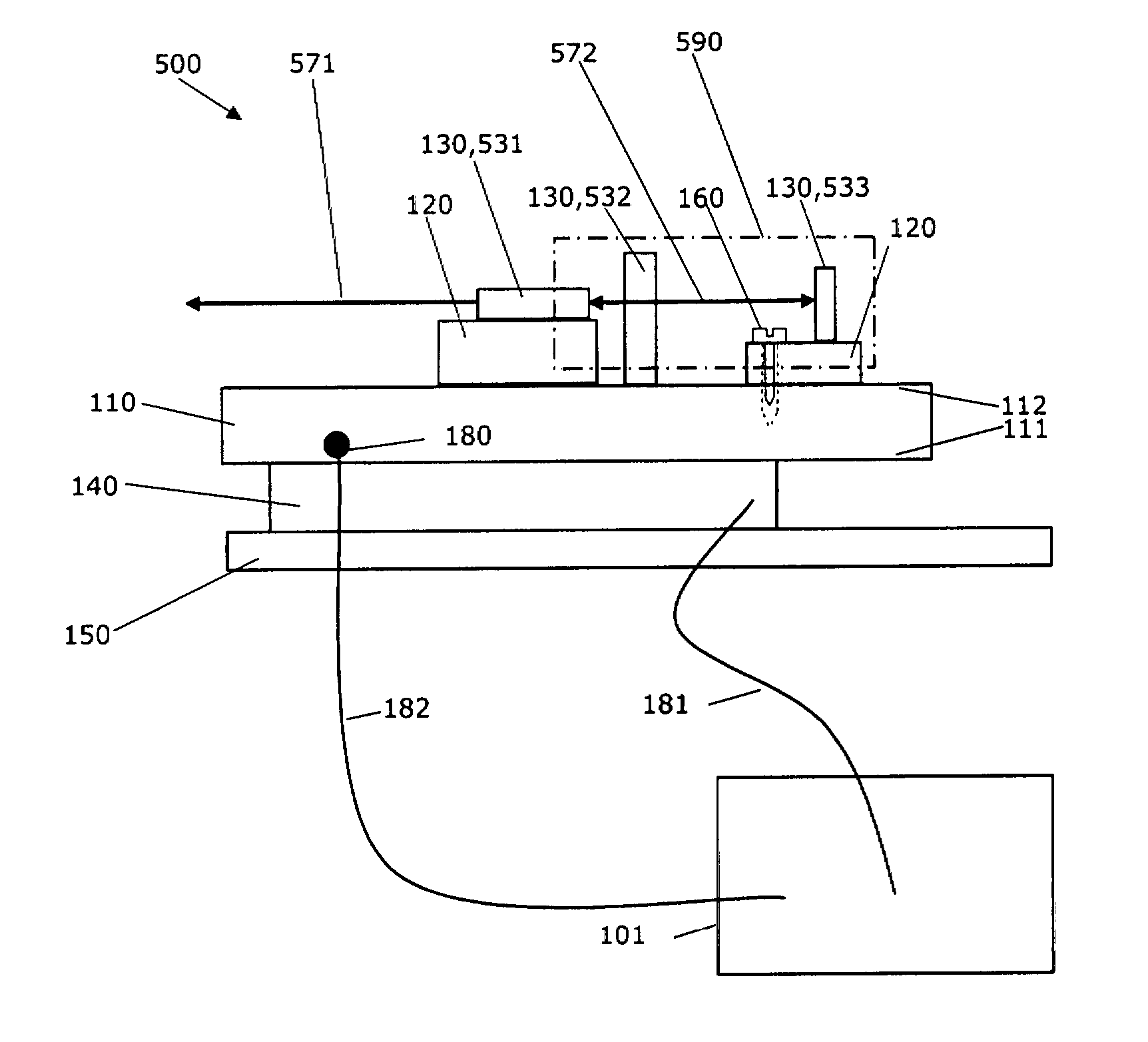
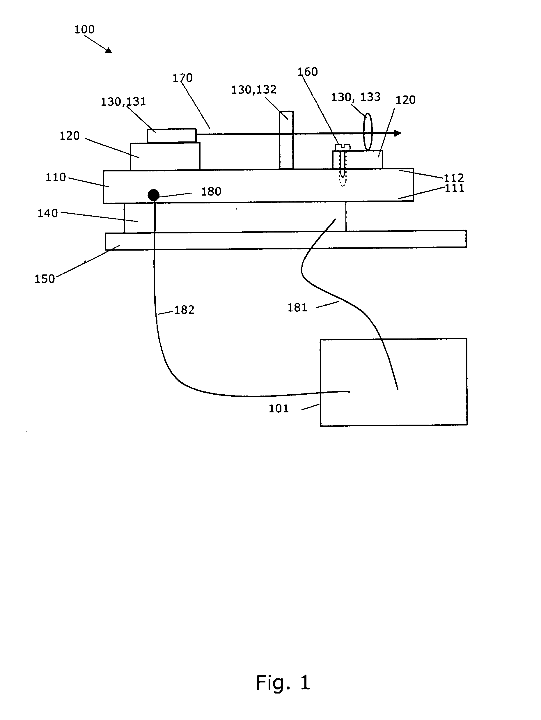
[0054]FIG. 1 is a principal sketch of a laser system comprising a semiconductor laser 100 and a temperature control system 101.

[0055] The semiconductor laser 100 comprises optical components 130 for instance semiconductor laser diodes, optical filters, gratings, mirrors, wave plates, lenses, frequency doubling crystals and electro-optic components. In FIG. 1, the semiconductor laser device is illustrated as comprising a semiconductor laser diode 131 which generates a beam 132 that is transmitted through an optical filter 132 and beam shaping optics 133. It should be understood that the semiconductor laser device 100 may contain other optical components, and that the semiconductor laser 100 can be of different types, including but not limited to: external cavity lasers, frequency doubled lasers, pumped lasers, pulsed lasers and semiconductor lasers comprising only a laser diode and beam shaping optics. Similarly, the semiconductor laser diode 131 can be of various types, including but


PUM


Abstract

A method for preserving a mechanical alignment of a semiconductor laser (100) by use of a temperature control system (101). The semiconductor laser includes an optical mount (110) for mounting a semiconductor laser diode (131) and optical components (132,133). A thermal device (140) and a temperature sensor (180) are used for heating or cooling the optical mount and the semiconductor laser. The method includes adjusting the temperature of the semiconductor laser at a rate less than a predetermined temperature rate by use of the thermal device so as to minimise temperature-related faults, wherein the predetermined temperature rate is experimentally determined and is adapted to the semiconductor laser.

Description


Claims


Application Information

Patent Timeline
Owner TORSANA LASER TECH
Why Eureka
Try Eureka