Skating Simulation Exercise Device

a simulation exercise and exercise device technology, applied in cardiovascular exercise devices, resilient force resistors, sports apparatuses, etc., can solve the problems of lack of this important inertial component in machines that employ weight stacks, hydraulic pistons or elastic cords for resistance, etc., to increase the resistance to rearward movement, reduce the amount of force transmitted, and increase the effect of force transmitted

Inactive Publication Date: 2008-02-21
EDMONDSON ROBERT
View PDF35 Cites 4 Cited by
  • Summary
  • Abstract
  • Description
  • Claims
  • Application Information

AI Technical Summary

Benefits of technology

The invention relates to a device that can transmit forces more effectively than just pulling on one leg support for better gait control during walking or running movements. This helps reduce muscle strain caused when wearing shoes due to weight distribution issues such as overweight legs.

Problems solved by technology

The technical problem addressed in this patents relates to improving athletic simulation equipment used during skiing without sacrificing stability and controllability over its movement.

Method used


Image

  • Skating Simulation Exercise Device
  • Skating Simulation Exercise Device
  • Skating Simulation Exercise Device

Examples


Embodiment Construction

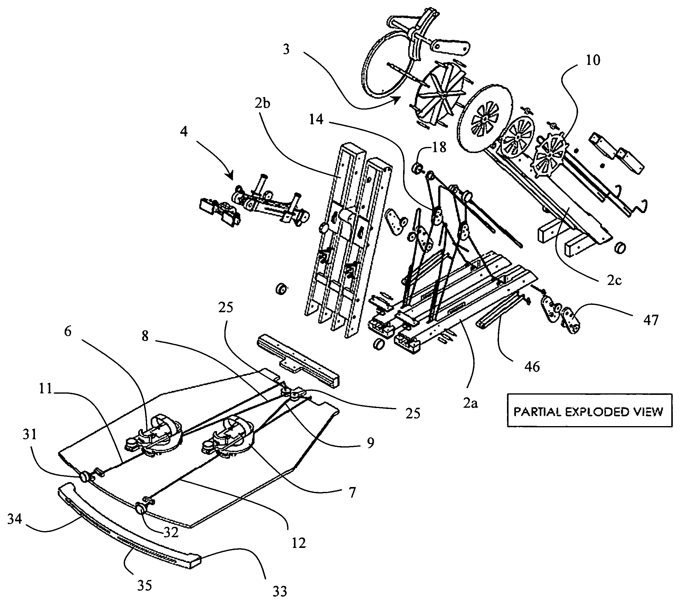
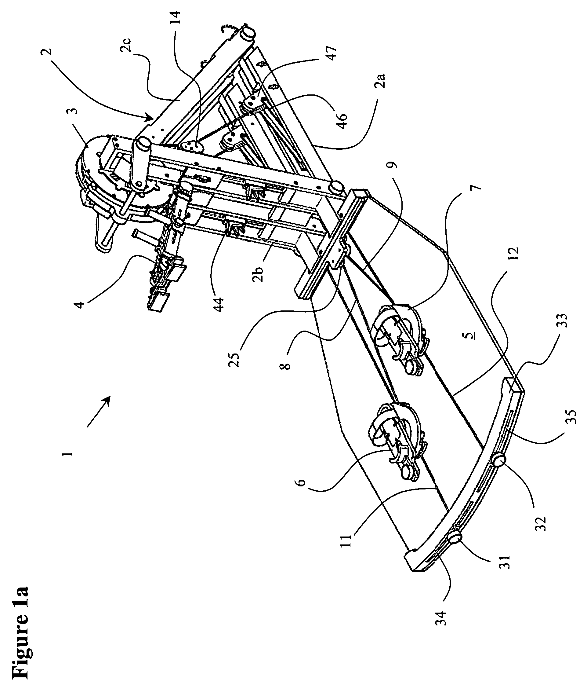
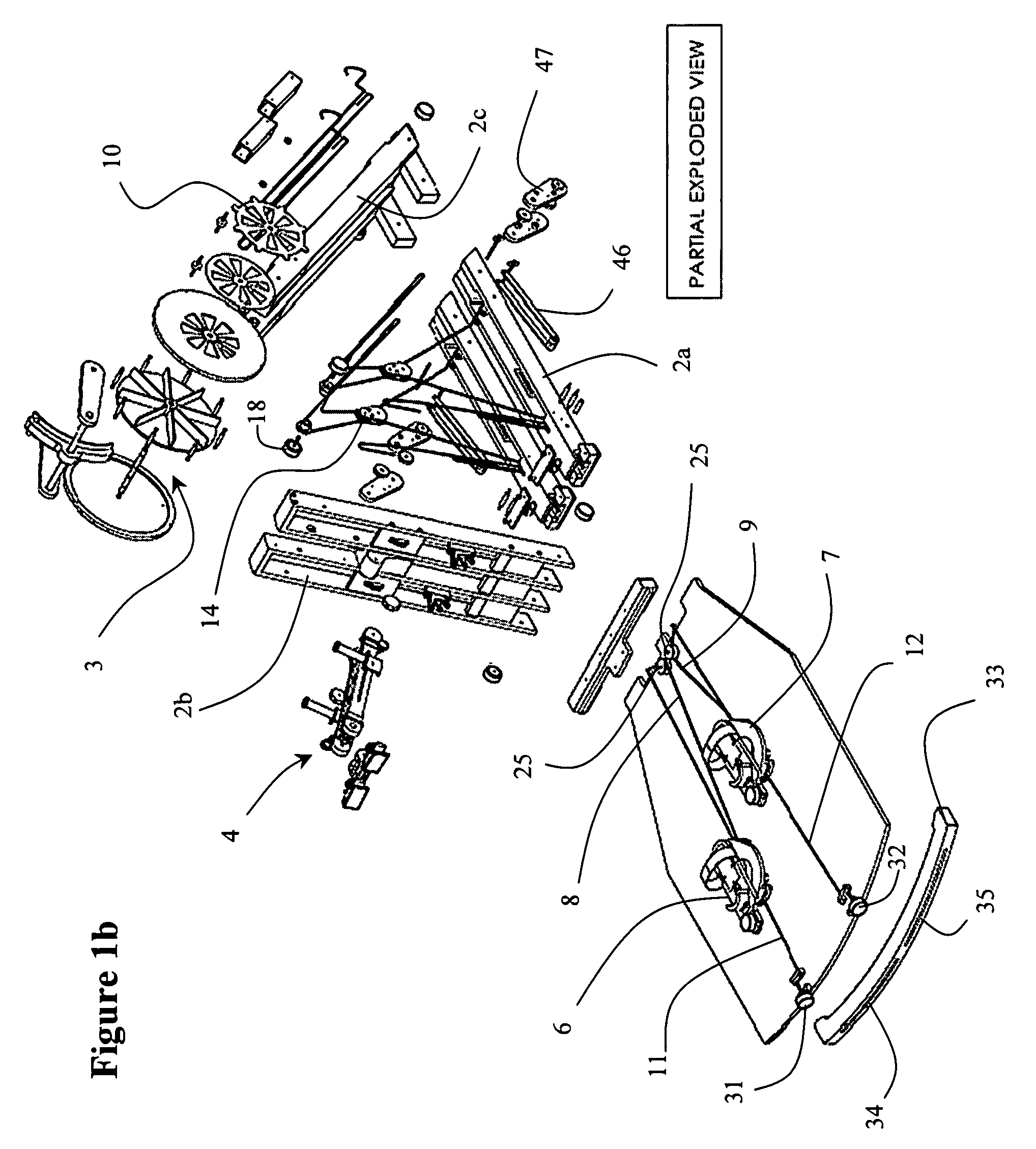
[0029]With reference to FIGS. 1a and 1b, the skating simulation exercising device 1, according to the present invention, includes a triangular frame 2 for mounting an inertial resistance apparatus, e.g. a flywheel 3, and an optional torso-supporting arm 4. Typically a smooth skating surface 5 is provided, which extends from the base of the frame 2, but an existing surface can be used, if the device 1 is permanently set up proximate a suitably smooth surface. Left and right sliding foot supports 6 and 7 are connected on the ends of left and right pull cables 8 and 9, respectively, and laterally confined by left and right guide cables 11 and 12, respectively. The resistance of the flywheel 3 can be adjusted by the rotation of vent covers 10, which regulate the amount of air that is passed through the vanes of the flywheel 3. The use of the flywheel 3 enables the user to stride until the flywheel 3 reaches a certain speed, i.e. revolutions per minute, pause for a period of time, i.e. simu


PUM


Abstract

The invention relates to a skating simulating exercise device including a force transmission means, which exponentially increases the amount of force required to spin a flywheel as the user approaches the limits of ovoid shaped boundaries, thereby eliminating abrupt stoppages and to simulate the digging in and pushing off actions in a real skating stride. The skating simulating exercise device also includes resistance to both rearward and lateral motion, which can be linked together to more effectively strengthen all aspects of a skater's motion.

Description


Claims


Application Information

Patent Timeline
Owner EDMONDSON ROBERT
Why Eureka
Try Eureka