Oven protection system for a thermo-forming machine

Inactive Publication Date: 2008-03-06
PETERSEN ALBERT O
View PDF27 Cites 3 Cited by
  • Summary
  • Abstract
  • Description
  • Claims
  • Application Information

AI Technical Summary

Benefits of technology

[0012]The present invention overcomes the deficiencies of the related art in an oven protection system for a thermo-forming machine that has a source of heat for heating a workpiece. The oven protection system includes a barrier that is movable from a stored position to a deployed position between the source of heat and the workpiece in response to a predetermined

Problems solved by technology

The screen is usually made of some sort of metallic material and because of its proximity to the heating elements, it generally becomes very hot during thermo-forming operations.
During any given thermo-forming process, it is possible that a workpiece may take more time in the mold to form and set up or the operator may take more time than anticipated to remove a final product from the clamp frame and to mount a new workpiece in the clamp frame.
Alternatively, a power outage, mechanical failure, or operator error may interrupt the cycling operation of the thermo-forming machine.
This causes the workpiece to further melt such that the now melting workpiece drips down into the heating elements of the oven.
When the melting workpiece comes into contact with the screen, heating elements, or other very hot portions of the oven, it can produce smoke, fire, and noxious fumes t

Method used


Image

  • Oven protection system for a thermo-forming machine
  • Oven protection system for a thermo-forming machine
  • Oven protection system for a thermo-forming machine

Examples


Embodiment Construction

)

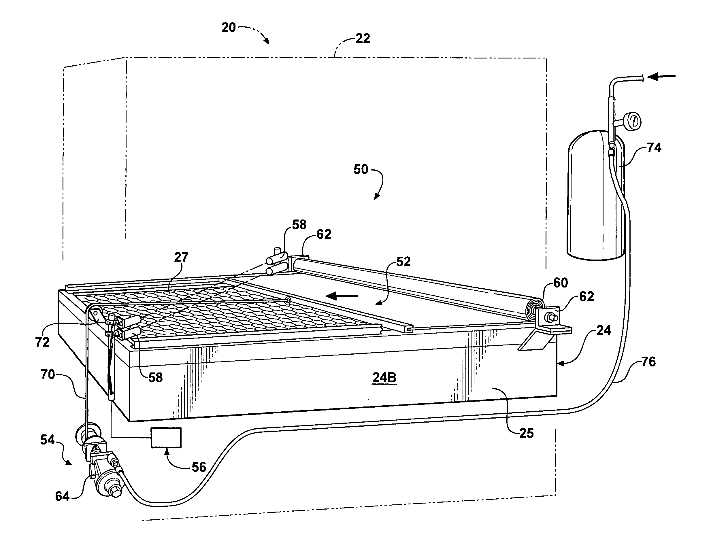
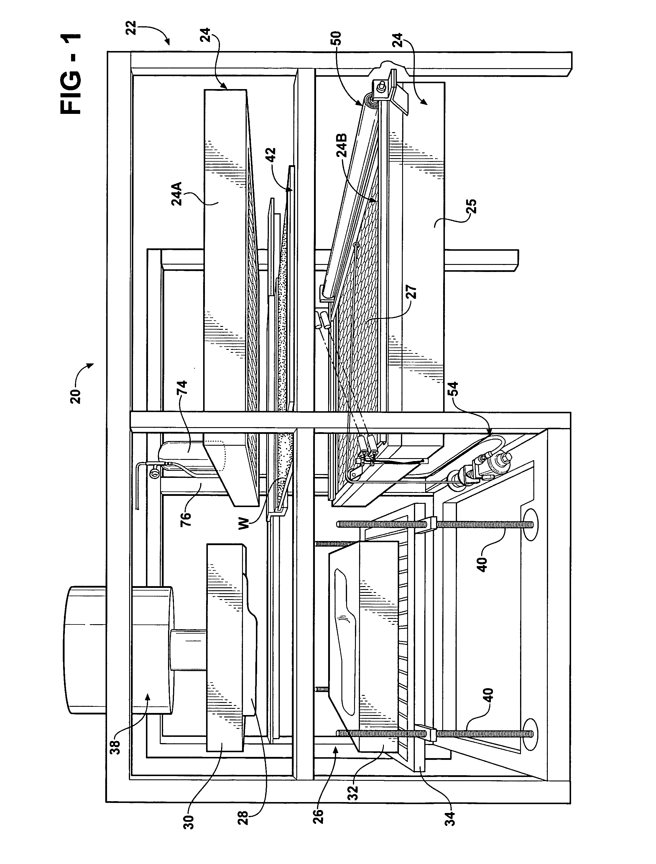
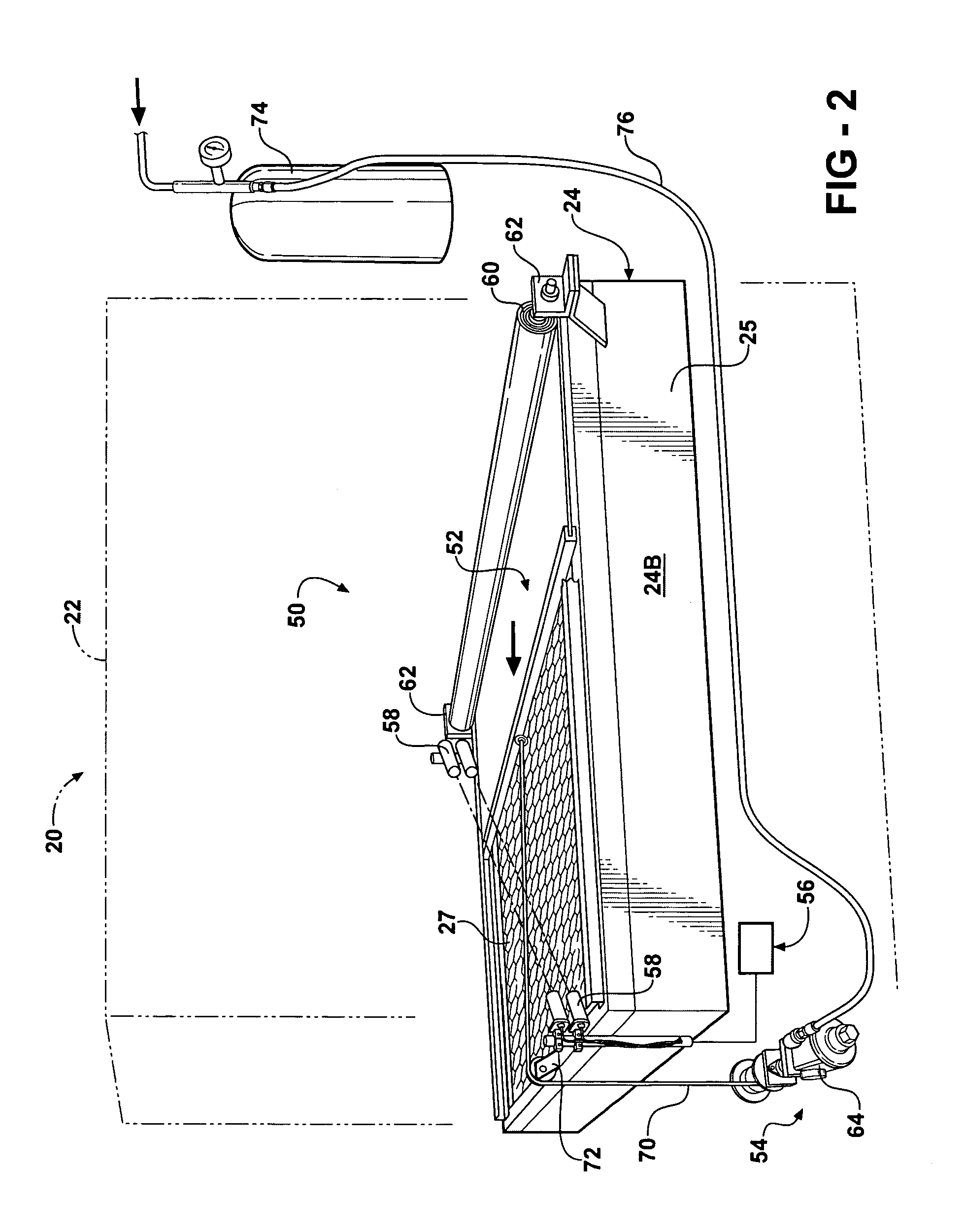
[0020]One representative example of a thermo-forming machine is generally indicated at 20 in FIG. 1. The thermo-forming machine 20 illustrated in this figure is conventional in many respects in that it includes a main superstructure, generally indicated at 22, which supports a source of heat, such as a convection or infrared oven, generally indicated at 24, and a mold assembly, generally indicated at 26. Thus, the oven may be gas-fired, electric or may use any other suitable source of heat of the type commonly known in the related art. In the representative example illustrated in FIG. 1, the oven 24 may include upper and lower sections 24A, 24B, respectively, that are employed to heat and ultimately plasticize the workpiece W. Each upper and lower sections 24A and 24B include a housing 25 in which is supported a plurality of heating elements. A screen 27 forms the upper portion of the lower oven section 24B. The thermo-forming machine 20 illustrated in FIG. 1 has a double-ended, shutt


PUM

PropertyMeasurementUnit
Pressureaaaaaaaaaa
Flexibilityaaaaaaaaaa
Heataaaaaaaaaa

Abstract

An oven protection system for a thermo-forming machine having a source of heat for heating a workpiece. The oven protection system includes a barrier that is movable from a stored position to a deployed position between the source of heat and the workpiece in response to a predetermined condition.

Description


Claims


Application Information

Patent Timeline
Owner PETERSEN ALBERT O
Why Eureka
Try Eureka