Systems and methods for electrical leakage detection

a leakage detection and detection system technology, applied in the direction of emergency protective arrangements for limiting excess voltage/current, instruments, electric devices, etc., can solve the problem of not addressing the detection of electrical leakage in a balanced fault condition, the fatigue or failure of a conductor's insulation of a machine component, and the leakage of electrical current from a high-voltage power supply to a machine fram

Active Publication Date: 2008-06-05
CATERPILLAR INC +1
View PDF19 Cites 44 Cited by
  • Summary
  • Abstract
  • Description
  • Claims
  • Application Information

AI Technical Summary

Benefits of technology

This patented describes systems used in machinery to prevent damage caused by electricity leaks from damaging equipment or causing safety hazards during use. These systems include two components: a power supply called a generator (G) and a mechanism called a load-carry unit (LCU). A balance fault occurs when there're no flow of energy through any conductive pathways within these units due to imperfections such as weld joint seams or insulation failures. When this happens, it can cause overvoltage conditions which could lead to explosions if they occur near people who might be touched down nearby. To solve this problem, various techniques have been developed including monitoring changes made along signal paths while still providing accurate results.

Problems solved by technology

This patented technical problem addressed in this patent relating to improving the accuracy and security of electronic devices used at different stages during their operation under various environmental factors like temperature changes, humidity levels, vibrations etc., which can cause damage due to electrostatic charge buildup. Existing solutions such as adding extra components to isolate certain parts of the electronics from external sources often result in increased costs compared to other alternatives. Therefore, improved techniques for accurately identifying leaks caused by these environments would enhance overall performance and efficiency of electronic equipment.

Method used


Image

  • Systems and methods for electrical leakage detection
  • Systems and methods for electrical leakage detection
  • Systems and methods for electrical leakage detection

Examples


Embodiment Construction

[0011]Reference will now be made in detail to the disclosed embodiments, examples of which are illustrated in the accompanying drawing. Wherever possible, the same reference numbers will be used in the drawing to refer to the same or like parts.

[0012]In the disclosed embodiments, a machine may refer to a petroleum-electric hybrid powered machine, such as a hybrid-electric vehicle which uses internal combustion engines and electric batteries, fuel cell, or other electrical power source to power electric motors. A machine may also refer to a machine with one or more electric motors and an electric power source such as an electric vehicle.

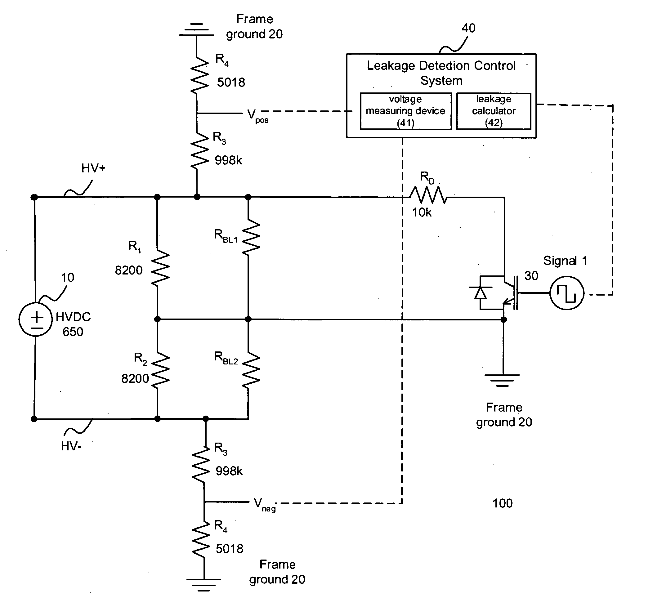
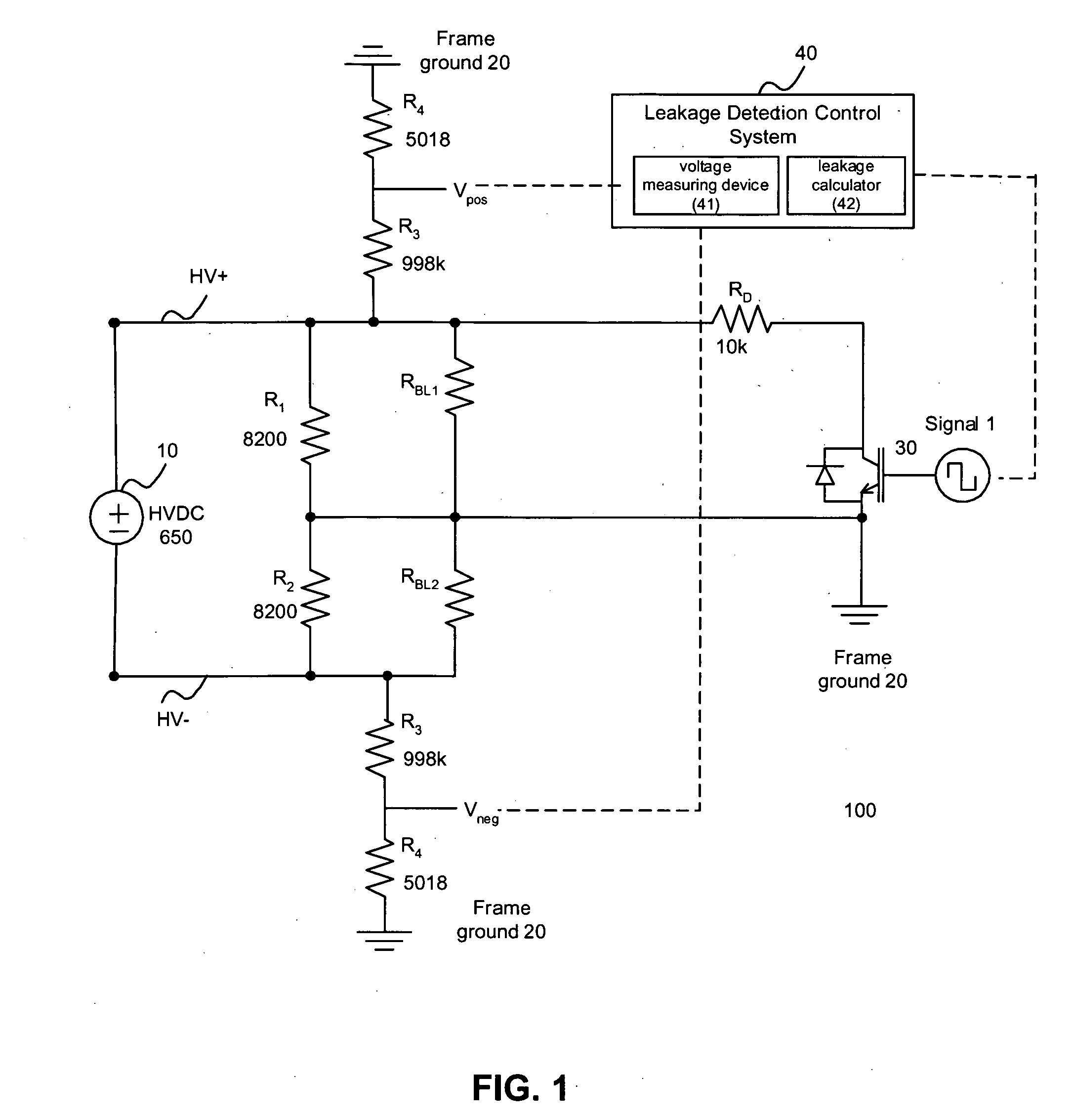
[0013]FIG. 1 illustrates an electrical leakage detection circuit 100 consistent with the disclosed embodiments. Electrical leakage detection circuit 100 may be used to detect the presence of an electrical leakage current between a terminal of a high voltage DC power supply and the frame of a machine. In one embodiment, a “frame” may refer to the conducti


PUM


Abstract

Systems and methods are disclosed for detecting balanced electrical leakage between a power source and a machine frame. In one embodiment, a balanced fault detection system for a machine includes a power source that is electrically insulated from a machine frame and a leakage detection switch that is connected to a ground. The balanced fault detection system also includes a leakage detection resistor that is interposed between a power source terminal and the switch having a leakage detection resistance. The balanced fault detection system further includes a voltage measuring device that measures voltages of the power source at positive and negative voltage sides of the ground and a leakage calculator that calculates a leakage resistance of the machine based on the measured voltages at the positive and negative voltage sides and the leakage detection resistance.

Description


Claims


Application Information

Patent Timeline
Owner CATERPILLAR INC
Why Eureka
Try Eureka