Gate Driver and Driving Method Thereof in Liquid Crystal Display

Active Publication Date: 2008-07-24
AU OPTRONICS CORP
View PDF10 Cites 38 Cited by
  • Summary
  • Abstract
  • Description
  • Claims
  • Application Information

AI Technical Summary

Benefits of technology

[0009]It is therefore an object of the present invention to provide a gate driver and a driving method thereof in a liquid crystal display to reduce the g

Problems solved by technology

In addition, because the cost of the driving integrated circuit for use in the liquid crystal display is high, using fewer driving integrated circuits without affecting the performance of the liquid crystal display can reduce the manufacturing cost.
By using the approach, many driving integrat

Method used


Image

  • Gate Driver and Driving Method Thereof in Liquid Crystal Display
  • Gate Driver and Driving Method Thereof in Liquid Crystal Display
  • Gate Driver and Driving Method Thereof in Liquid Crystal Display

Examples


Embodiment Construction

[0022]Detailed illustrative embodiments of the present invention are disclosed herein. However, specific details disclosed herein are merely representative for purposes of describing exemplary embodiments of the present invention. This invention may, however, be embodied in many alternate forms and should not be construed as limited to the embodiments set forth herein.

[0023]The present invention is directed to a gate driver and a driving method thereof for use in a liquid crystal display, which are capable of saving the gate driving integrated circuits and outputting the driving signals capable of saving the data driving integrated circuits, so as to reduce the production cost.

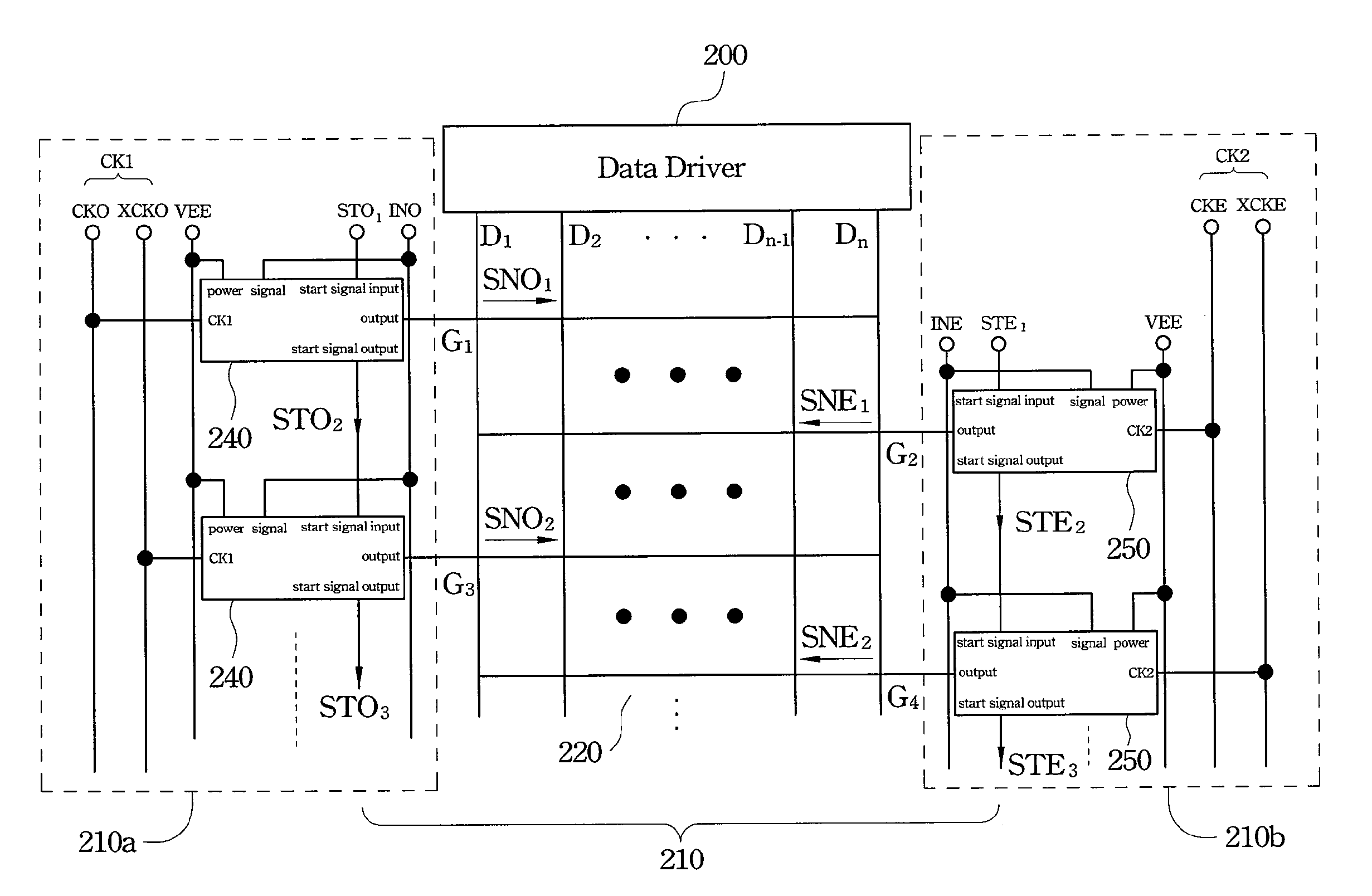
[0024]FIG. 2 is a diagram showing a liquid crystal display panel according to one embodiment of the present invention. The liquid crystal display panel includes a plurality of data lines D1 . . . Dn, a plurality of gate lines G1 . . . Gn, a data driver 200 and a gate driver 210. The gate driver 210 is used to dri


PUM


Abstract

A gate driver includes several first and second circuit units outputting first and second driving signals to odd and even gate lines, respectively, and each of the first circuit units or the second circuit units includes a signal output unit for outputting the driving signal and a shift register unit for outputting a start signal to a next circuit unit. A driving method is also disclosed.

Description


Claims


Application Information

Patent Timeline
Owner AU OPTRONICS CORP
Why Eureka
Try Eureka