Multicasting system, client device, upper router controller, method of displaying content and computer program
- Summary
- Abstract
- Description
- Claims
- Application Information
AI Technical Summary
Benefits of technology
Problems solved by technology
Method used
Image

Examples
first embodiment
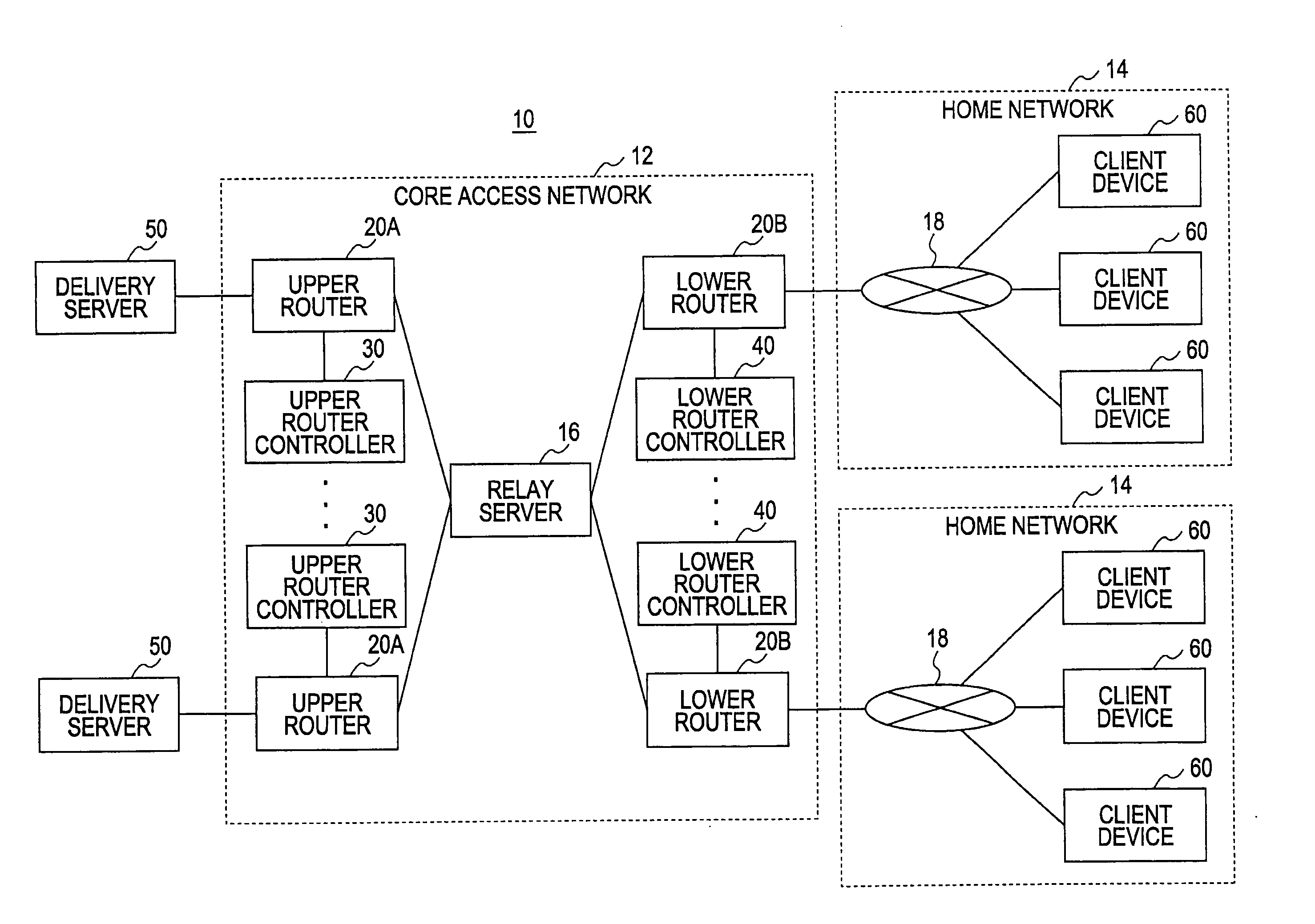
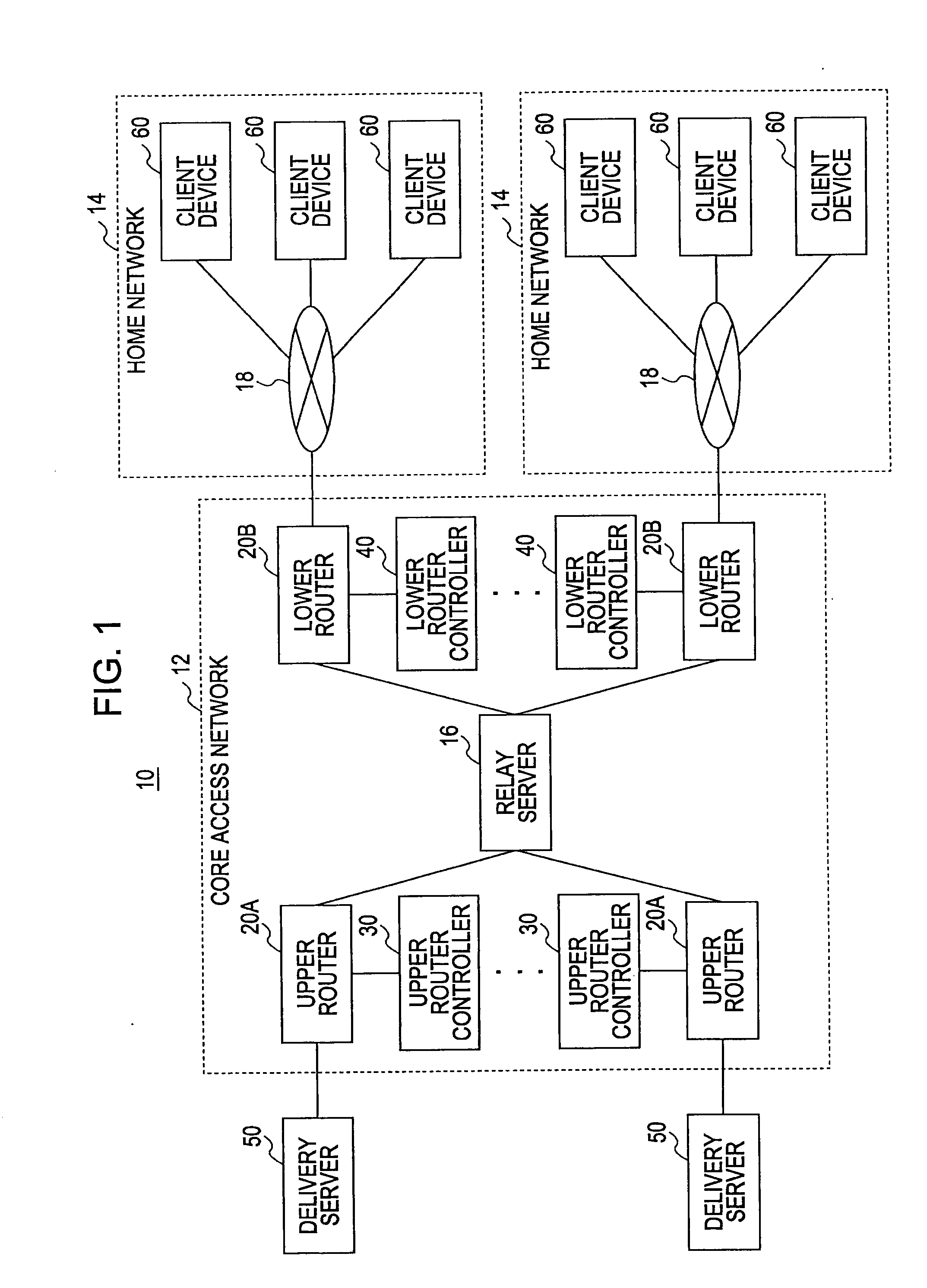
[0058]A multicasting system 10 of a first embodiment of the present invention is described below. FIG. 1 illustrates the multicasting system 10 in accordance with the first embodiment of the present invention. The multicasting system 10 includes a core access network 12, a home network 14 and a delivery server 50.
[0059]The term “multicast delivery” means a one-to-multi-point delivery in which a content is delivered from a single delivery server to multiple client devices. A group of programs (contents) multicast is referred to as a multicast group.
[0060]The core access network 12 serves as a relay network working between the home network 14 and the delivery server 50. The core access network 12 includes a plurality of routers 20 and a relay server 16 corresponding to the home network 14. The delivery server 50 is linked to the core access network 12 via an upper router 20A while the core access network 12 is linked to the home network 14 via a lower router 20B.
[0061]The relay server 16
second embodiment
[0177]A second embodiment of the present invention is described in detail below with reference to FIGS. 18 through 27A-27C. In accordance with the second embodiment of the present invention, the IPTV server 50 functions as a delivery server and the IPTV terminal 60 functions as a client device.
[0178]In typical channel switching, a channel currently displayed on a main screen (entire screen) is switched to a next channel on the main screen in response to a selection of a channel switching button (command). The channel switching overhead to the next channel cannot be predicted and an impatiently long waiting time can result.
[0179]As described with reference to the first embodiment of the present invention, the channel switching overhead can be reduced by participating beforehand in the multicast group having a constantly high hit ratio. A more comfortable zapping operation may be performed by accounting for the size of the overhead during the selection of a target session in the zapping
PUM
 Abstract
Description
Claims
Application Information
 - R&D Engineer
- R&D Manager
- IP Professional
- Industry Leading Data Capabilities
- Powerful AI technology
- Patent DNA Extraction
Browse by: Latest US Patents, China's latest patents, Technical Efficacy Thesaurus, Application Domain, Technology Topic.
© 2024 PatSnap. All rights reserved.Legal|Privacy policy|Modern Slavery Act Transparency Statement|Sitemap