Image processing apparatus
- Summary
- Abstract
- Description
- Claims
- Application Information
AI Technical Summary
Benefits of technology
Problems solved by technology
Method used
Image

Examples
first embodiment
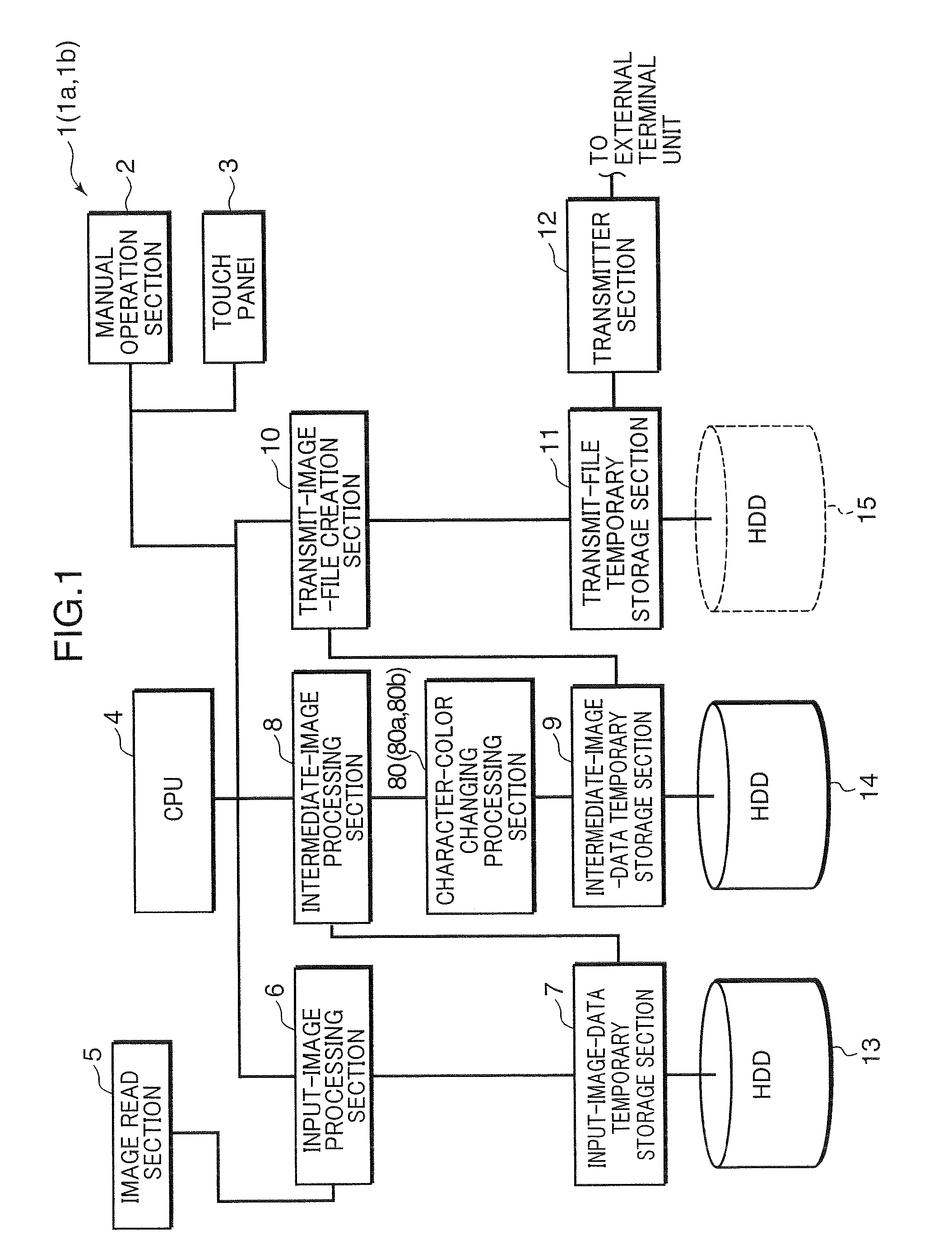
[0035]FIG. 1 is a block diagram showing the configuration of a scanner apparatus which is one example of an image processing apparatus, according to a first embodiment of the present invention. The scanner apparatus 1 illustrated in FIG. 1 comprises a manual operation section 2, a touch panel 3 (serving as a display section), a CPU (Central Processing Unit) 4, an image read section 5, an input-image processing section 6, an input-image-data temporary storage section 7, an intermediate-image processing section 8, a character-color changing processing section 80, an intermediate-image-data temporary storage section 9 (serving as a storage section), a transmit-image-file creation section 10 (serving as a combined-data creation section), a transmit-file temporary storage section 11, a transmitter section 12, and two HDDs (Hard Disk Drives) 13, 14. The image processing apparatus subject to the present invention may be a complex machine provided, for example, by adding an image forming secti
second embodiment
[0113]A scanner apparatus la according to a second embodiment of the present invention will be described below. The scanner apparatus la is different from the scanner apparatus 1 in respective operations of a first preview control section 81a, a color-designation acceptance section 83a and a color-change processing section 84a in a character-color changing processing section 80a illustrated in FIG. 4.
[0114]FIG. 15 is a flowchart showing one example of an operation of the character-color changing processing section 80a and associated sections in the scanner apparatus 1a according to the second embodiment. FIG. 16 is a schematic diagram for explaining an operation of the character-color changing processing section 80a. Based on the color image data 61 comprising the multivalued image data 63, the character image data 62 and the color information 66 which are stored in the intermediate-image-data temporary storage section 9, the first preview control section 81a causes the touch panel 3 t
third embodiment
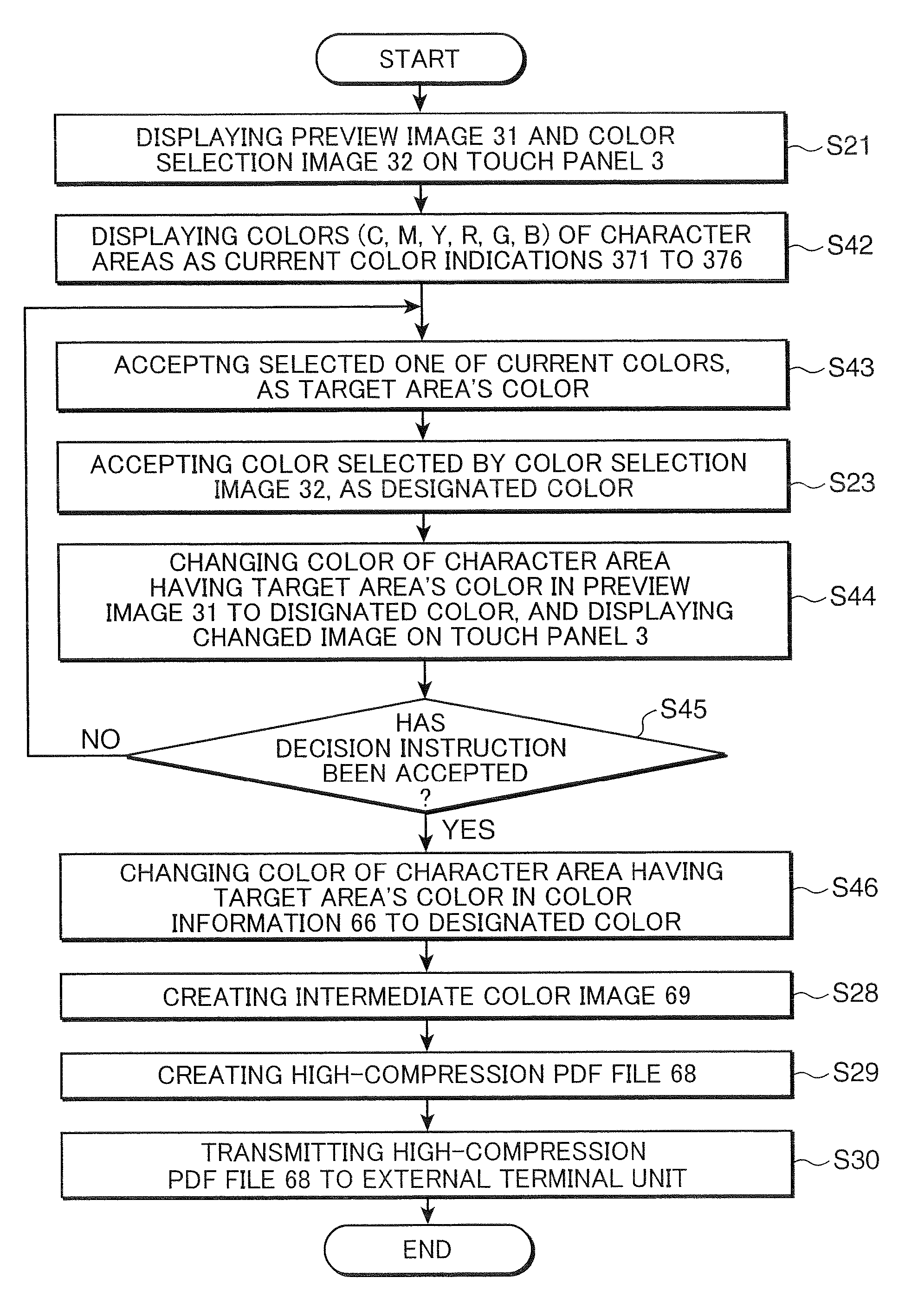
[0123]A scanner apparatus 1b according to a third embodiment of the present invention will be described below. The scanner apparatus 1b illustrated in FIG. 1 is different from the scanner apparatus 1 in the configuration of a character-color changing processing section 80b. FIG. 17 is a block diagram showing one example of the configuration of the character-color changing processing section 80b. Specifically, the scanner apparatus 1b illustrated in FIG. 1 is different from the scanner apparatus 1 in that the character-color changing processing section 80b further includes a current-color selection display control section 89 and a target area's color acceptance section 90, and in respective operations of a color-designation acceptance section 83b, a color-change processing section 84b and a second preview control section 85b.
[0124]FIG. 18 is a flowchart showing one example of the operation of the character-color changing processing section 80b and associated sections, and FIG. 19 is a
PUM
 Abstract
Description
Claims
Application Information
 - R&D Engineer
- R&D Manager
- IP Professional
- Industry Leading Data Capabilities
- Powerful AI technology
- Patent DNA Extraction
Browse by: Latest US Patents, China's latest patents, Technical Efficacy Thesaurus, Application Domain, Technology Topic.
© 2024 PatSnap. All rights reserved.Legal|Privacy policy|Modern Slavery Act Transparency Statement|Sitemap