Fastening Unit for Ignition Units and Device for Carbon Deposition

a technology of fastening unit and ignition unit, which is applied in the direction of vacuum evaporation coating, plasma technique, gas-filled discharge tube, etc., can solve the problems of low deposition rate, difficult control of dc arc vaporization of carbon, and inconvenient economic use of methods, etc., to achieve simple exchange of ignition unit and rapid exchanging

Inactive Publication Date: 2008-10-16
ROBERT BOSCH GMBH
View PDF5 Cites 0 Cited by
  • Summary
  • Abstract
  • Description
  • Claims
  • Application Information

AI Technical Summary

Benefits of technology

The purpose of this new design allows for easy replacement of existing igniting devices by changing their positioning with respect to the surface being treated during treatment on substrates like semiconductor wafers. This makes it easier to maintain and monitor these devices more efficiently while also simplifying the process involved when replacing them.

Problems solved by technology

Technologies described involve techniques such as laser evaporation, electric spark ion formation, gasification processes, etc. These technics have their own advantages but they may require further improvements due to factors like cost efficiency, productivity, and quality control issues associated with current coatings systems.

Method used


Image

  • Fastening Unit for Ignition Units and Device for Carbon Deposition
  • Fastening Unit for Ignition Units and Device for Carbon Deposition
  • Fastening Unit for Ignition Units and Device for Carbon Deposition

Examples


Embodiment Construction

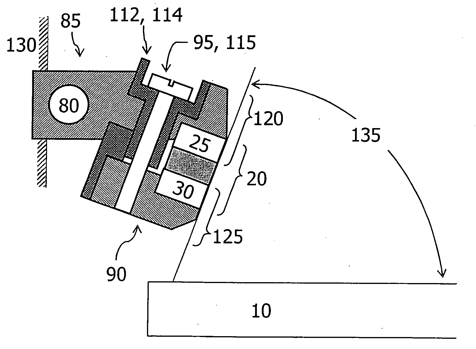
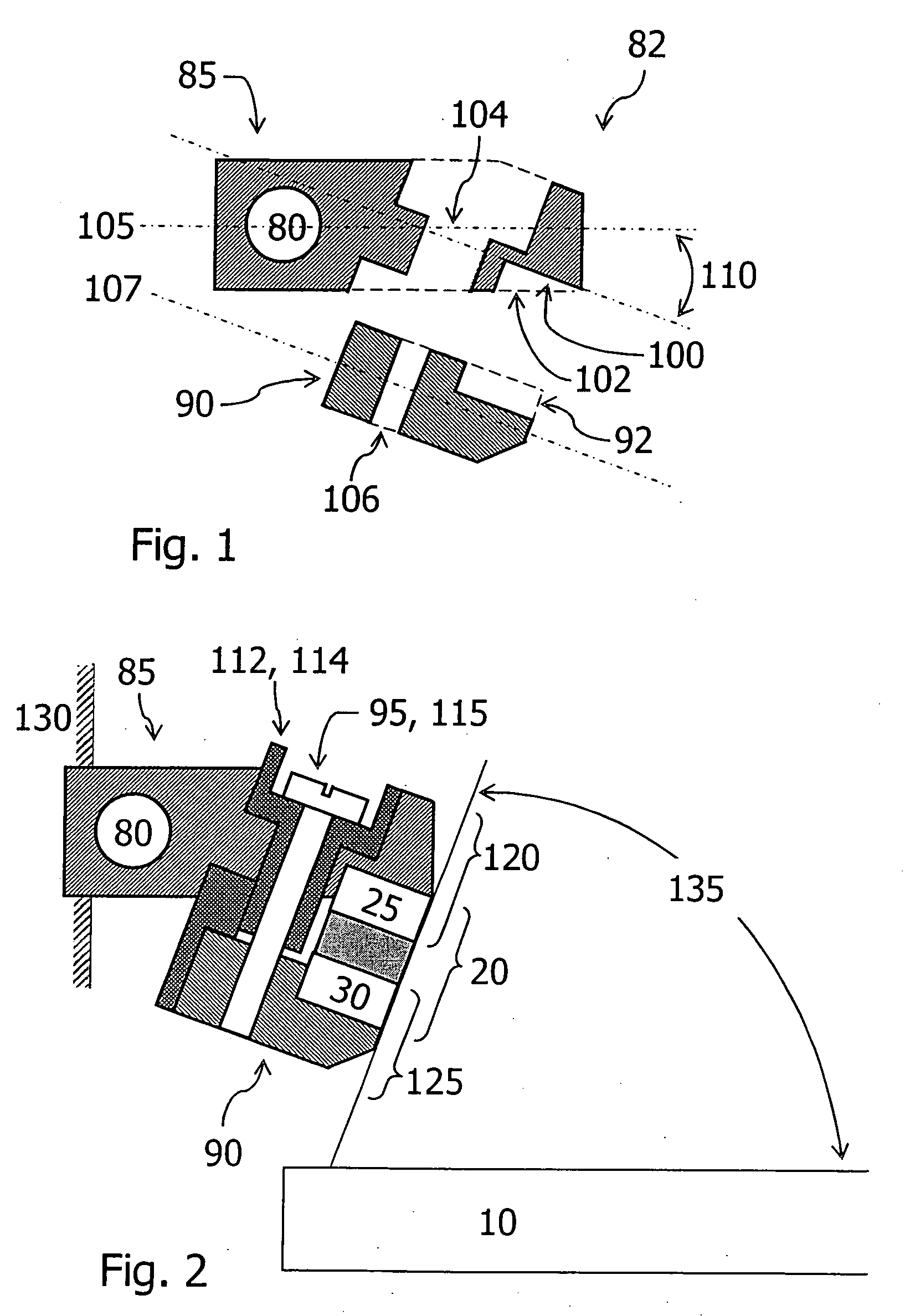
[0019]The fastening unit 82 shown in cross-section in FIG. 1 for an ignition unit, in particular of a carbon deposition device, has a first and second holder 85, 90. The two holders 85, 90 are held together by a fastening device 95, as is shown in FIG. 2. For both holders 85, 90, the length extension is greater than the thickness extension. As is shown in FIG. 1, the respective longitudinal axes 105, 107 run along the longitudinal extension of each holder 85, 90. The absolute length of first holder 85 is typically greater than that of second holder 90.

[0020]First holder 85 has a first bore 104 that runs continuously through the thickness of holder 85. Bore 104 is stepped, and has a center section having a smaller diameter. Bore 104 runs at an incline to the surface of holder 85 or to longitudinal axis 105. In addition, at an end area in the longitudinal extension of holder 85 a recess 102 is formed and is open toward second holder 90. Here, recess 102 has a shape such that recess 102 f


PUM

PropertyMeasurementUnit
Angleaaaaaaaaaa
Angleaaaaaaaaaa
Angleaaaaaaaaaa

Abstract

A fastening unit for fastening ignition units as part of a device for carbon deposition is provided, the fastening unit of the device having a first and a second holder, the ignition unit being situated between the two holders, and the holders being held together by at least one fastening device. The first holder has a first plane that has a first angle between 0° and 45° in relation to the longitudinal axis of the first holder. The ignition unit is situated such that the end surface of the ignition unit forms a right angle to the first plane.

Description


Claims


Application Information

Patent Timeline
Owner ROBERT BOSCH GMBH
Why Eureka
Try Eureka