Hybrid driving apparatus with multistage transmission provided in power transmission path and control method thereof

Inactive Publication Date: 2008-10-16
TOYOTA JIDOSHA KK +1
View PDF9 Cites 22 Cited by
  • Summary
  • Abstract
  • Description
  • Claims
  • Application Information

AI Technical Summary

Benefits of technology

[0009]The present invention was made to solve such a problem, and its object is to provide a hybrid driving apparatus capable of protecting portions generating driving force even when transmission stage is switched to a low-speed side, and to provide a method of controlling the same.

Problems solved by technology

Therefore, even if the transfer device is switched to the low-speed side, engine sound or vibration associated with the engine operation hardly increases.
As a result, it might be often the case that the driver is unaware that the vehicle is traveling with the low-speed side gear stage.
It is possible that driving continues for a long period of time while the transfer device is kept set to the low-speed side transmission stage.
It is concerned that the speed of rotation of electric motor might exceed tolerable rotation speed, or there might be excessive load on the electric motor or a power converter supplying electric power to the electric motor.

Method used


Image

  • Hybrid driving apparatus with multistage transmission provided in power transmission path and control method thereof
  • Hybrid driving apparatus with multistage transmission provided in power transmission path and control method thereof
  • Hybrid driving apparatus with multistage transmission provided in power transmission path and control method thereof

Examples


Example

[0029]An embodiment of the present invention will be described in detail with reference to the figures. In the figures, the same or corresponding portions are denoted by the same reference characters and description thereof will not be repeated.

[0030](Overall Configuration of Hybrid Driving Apparatus)

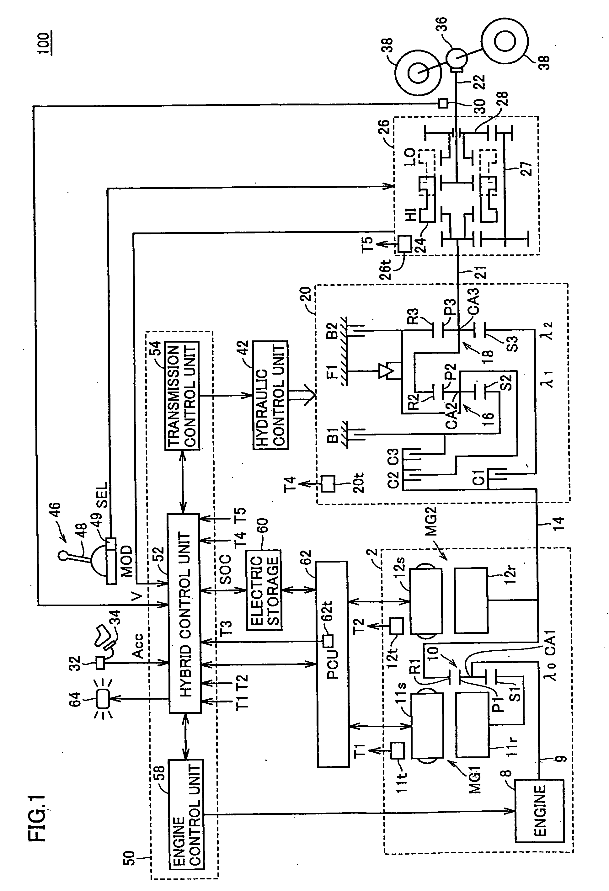
[0031]Referring to FIG. 1, a hybrid driving apparatus 100 in accordance with an embodiment of the present invention includes a power unit 2, a main transmission mechanism 20, a sub transmission mechanism 26, a rotation driving shaft 22, a differential gear 36, and driving wheels 38. Hybrid driving apparatus 100 is particularly suitable for an FR (Front engine Rear drive) vehicle.

[0032]It is noted that portions other than engine 8 of power unit 2 and sub transmission mechanism 26 are formed in symmetry with respect to the shaft center. In FIG. 1, portions representing power unit 2 and main transmission mechanism 20 on the lower side are not described.

[0033]Hybrid driving apparatus 100 furth


PUM


Abstract

When a sub transmission mechanism is switched to the LO-side gear stage, a hybrid control unit executes a control operation such that vehicle speed does not exceed limit vehicle speed determined in advance in accordance with the transmission gear ratio of LO-side gear stage. Specifically, the hybrid control unit reduces at least one of the driving torque generated by the engine and the second motor generator, so that rotation speed of the second motor generator does not exceed tolerable rotation speed. Further, the hybrid control unit reduces at least one of the driving torque generated by the engine and the second motor generator when any of temperatures respectively detected by temperature sensors exceed corresponding upper limit temperatures.

Description


Claims


Application Information

Patent Timeline
Owner TOYOTA JIDOSHA KK
Why Eureka
Try Eureka