Electrical Communication Switch, Outlet, Companion Device, and System

a technology of electrical communication switch and companion device, which is applied in the direction of coupling device connection, coupling protective earth/shielding arrangement, manufacturing tools, etc., and can solve the problem of high labor cost of wiring installation

Active Publication Date: 2008-10-23
HODJONAS JOEL
View PDF11 Cites 62 Cited by
  • Summary
  • Abstract
  • Description
  • Claims
  • Application Information

AI Technical Summary

Benefits of technology

In this patent, there are two technical features: 1. An electric switch with a transmitter and antenna attached to it. This allows users to remotely turn on or off the switch by sending signals over wireless communication channels like radio waves. 2. A switch control device is used to allow users to control the status of the switch. It has a cover that completely covers the switch's surface when removed.

Problems solved by technology

This patent describes different ways to connect electrical switches and electrical outlets to each other. However, traditional methods require direct wires, making it difficult to change any one outlet while maintaining its original function. Therefore, there is a technical problem addressed in this patent text where the goal is to create an electrical switch and electrical outlet that can simplify wiring and make changes more convenient.

Method used


Image

  • Electrical Communication Switch, Outlet, Companion Device, and System
  • Electrical Communication Switch, Outlet, Companion Device, and System
  • Electrical Communication Switch, Outlet, Companion Device, and System

Examples


Embodiment Construction

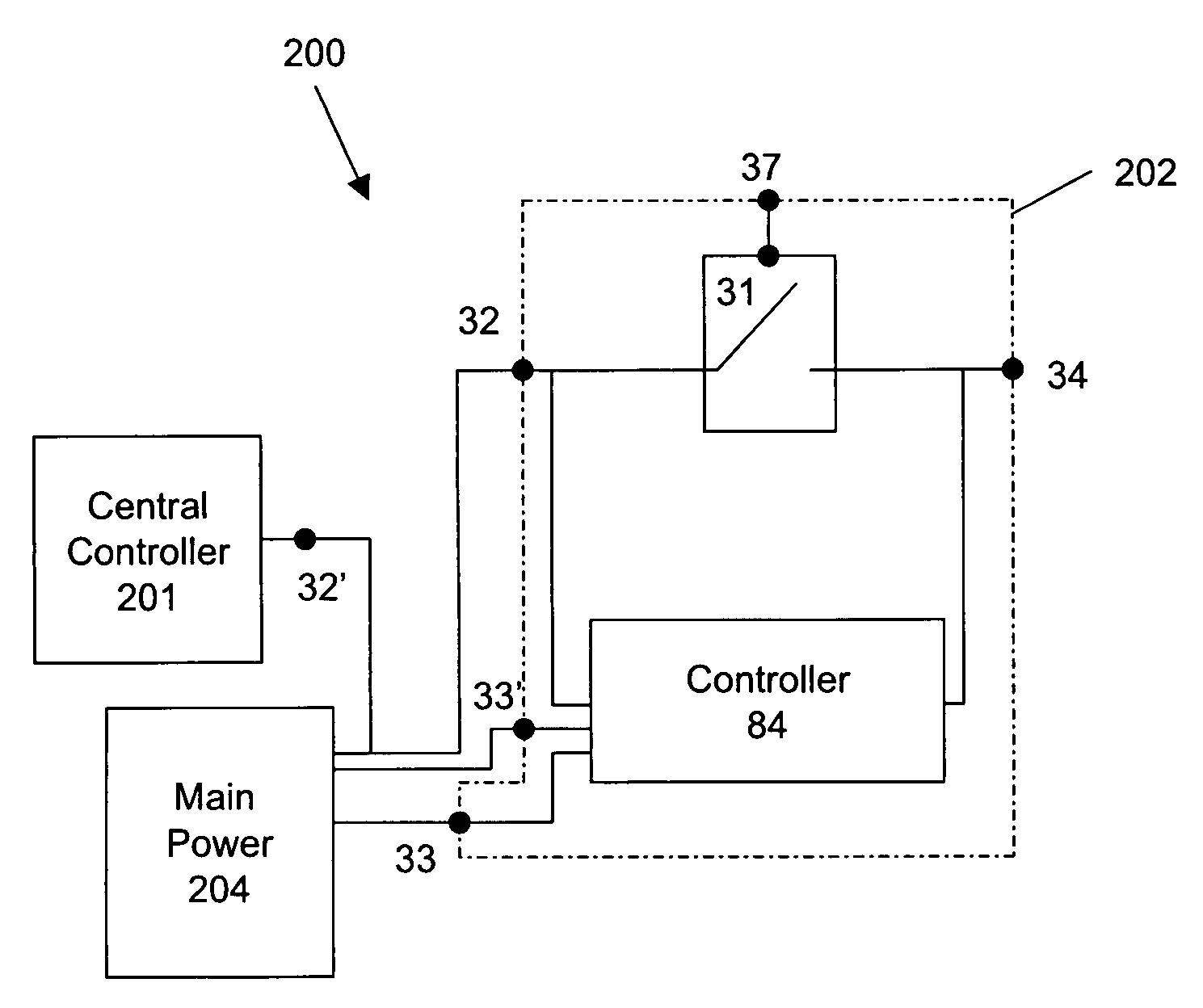
[0082]FIG. 2a and FIG. 2b are circuit block diagrams of an electrical communication system including an electrical communication switch 202 according to exemplary embodiments of the present invention. As depicted in FIG. 2a, the electrical communication system 200 includes main power 204 (i.e., a power source), central controller 201, and electrical switch 202. Electrical switch 202 includes a controller 84, a switch 31, a power lead 32 coupled to the switch 31 and to the controller 84, a manual switch lead 34 coupled to the other end of the switch 31 and to the controller 84, a ground lead 37 for allowing metal casing of the electrical switch 202 to be grounded, and a neutral lead 33 coupled to the controller 84. Switch 31 may be a mechanical switch; a solenoid switch, which is a specific type of relay that internally uses an electromechanical solenoid to operate an electrical switch; or a transistor switch. Switch 31 is controlled by a user and may be controlled manually or remotely


PUM

PropertyMeasurementUnit
Electric potential / voltageaaaaaaaaaa

Abstract

An electrical communication switch, an electrical communication outlet, an electrical communication companion device, and an electrical communication system are provided. The electrical communication switch includes a user-controlled switch having a plurality of switch leads and a controller. The controller is coupled to the user-controlled switch. The controller is configured to determine a change of state of the switch, and upon determining the switch has changed state to a new state, to send a signal. The electrical communication outlet includes a socket having a plurality of socket slots, at least one controlled switch, and a controller. The controller is coupled to said at least one controlled switch and is configured to receive a signal and to change a state of at least one of said at least one controlled switch pursuant to the signal.

Description


Claims


Application Information

Patent Timeline
Owner HODJONAS JOEL
Why Eureka
Try Eureka