Projection apparatus using variable light source

a technology of projection apparatus and light source, applied in the field of projection apparatus, can solve the problems of limitation and difficulty of high-quality image display, adverse effect of image quality, and limitation of display quality

Active Publication Date: 2009-02-26
IGNITE INC +1
View PDF26 Cites 30 Cited by
  • Summary
  • Abstract
  • Description
  • Claims
  • Application Information

AI Technical Summary

Benefits of technology

The technical effect of this patented technology is that it allows for better control over how much gray can be displayed on an image projected onto a screen by means of a special type of device called a digital microscope (DSM). This helps to improve the quality of images produced by the imaging system.

Problems solved by technology

This patent describes various techniques for improving the performance of projection apparatuses. One technique involves reducing the size of pixels in order to increase the resolution of the display. However, current methods result in reduced contrast ratios and decreased grayscale capabilities. Additionally, existing light sources like LEDs require a lot of power and cannot provide higher resolutions without increasing costs.

Method used


Image

  • Projection apparatus using variable light source
  • Projection apparatus using variable light source
  • Projection apparatus using variable light source

Examples


Embodiment Construction

[0060]A description of the mirror device, as the premise upon which the embodiment of the present invention is based, follows. Thereafter, a description of a preferred embodiment of the present invention is presented.

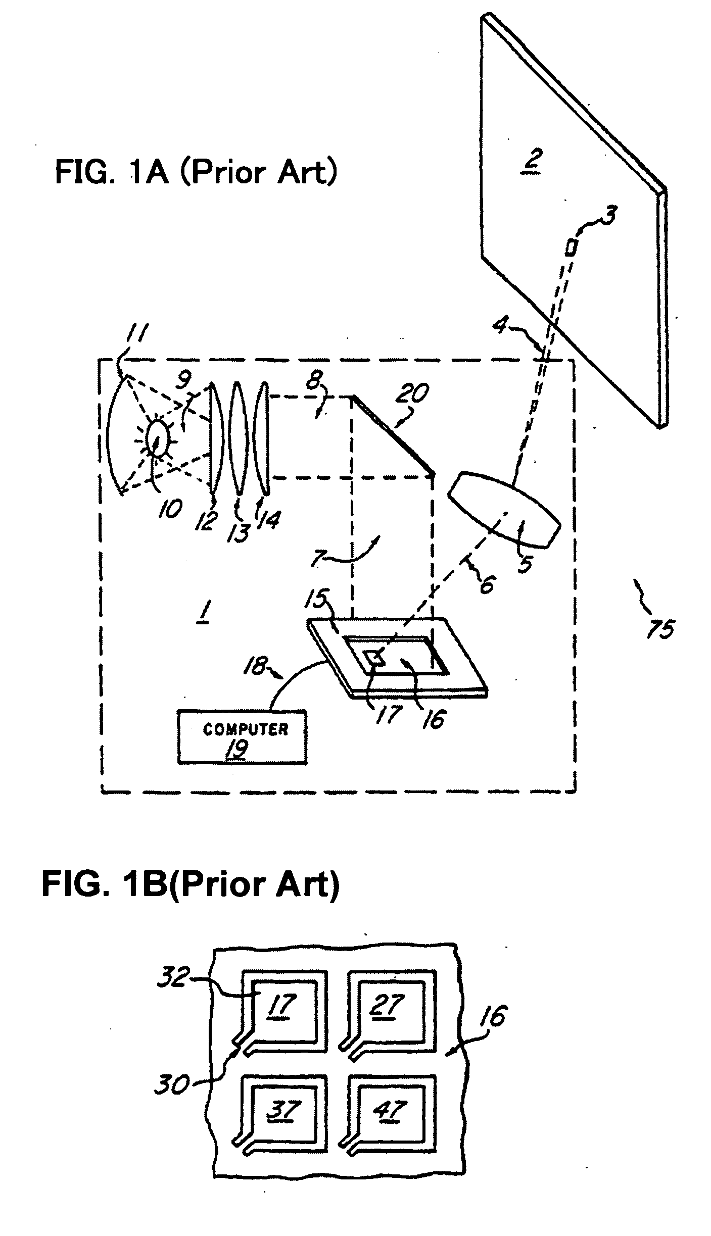
[0061]Projection apparatuses using a spatial light modulator, such as a transmissive liquid crystal, a reflective liquid crystal, a mirror array, etc., are widely known.

[0062]A spatial light modulator includes a two-dimensional array that arranges, enlarges, and then displays on a screen by way of a projection lens arrayed as tens of thousands to millions of miniature modulation elements for projecting individual pixels corresponding to an image.

[0063]The spatial light modulators generally used for projection apparatuses are of primarily two types: 1) a liquid crystal device for modulating the polarizing direction of incident light; a liquid crystal is sealed between transparent substrates and provides them with a potential, and 2) a mirror device that deflects miniature m


PUM


Abstract

A projection apparatus using a spatial light modulator (SLM), comprising the following: at least one variable light source, at least one spatial light modulator for modulating the illumination light emitted from the variable light source in accordance with the modulation state of arrayed pixel elements, a variable light source controller for controlling modulation of the variable light source, and a spatial light modulator controller for controlling modulation of each pixel element of the spatial light modulator, wherein the variable light source controller controls the variable light source so as to reduce the period in which the modulation states of the pixel element are in transition on a display image.

Description


Claims


Application Information

Patent Timeline
Owner IGNITE INC
Why Eureka
Try Eureka