Light-emitting diode light source and light-emitting diode lamp
- Summary
- Abstract
- Description
- Claims
- Application Information
AI Technical Summary
Benefits of technology
Problems solved by technology
Method used
Image

Examples
first embodiment
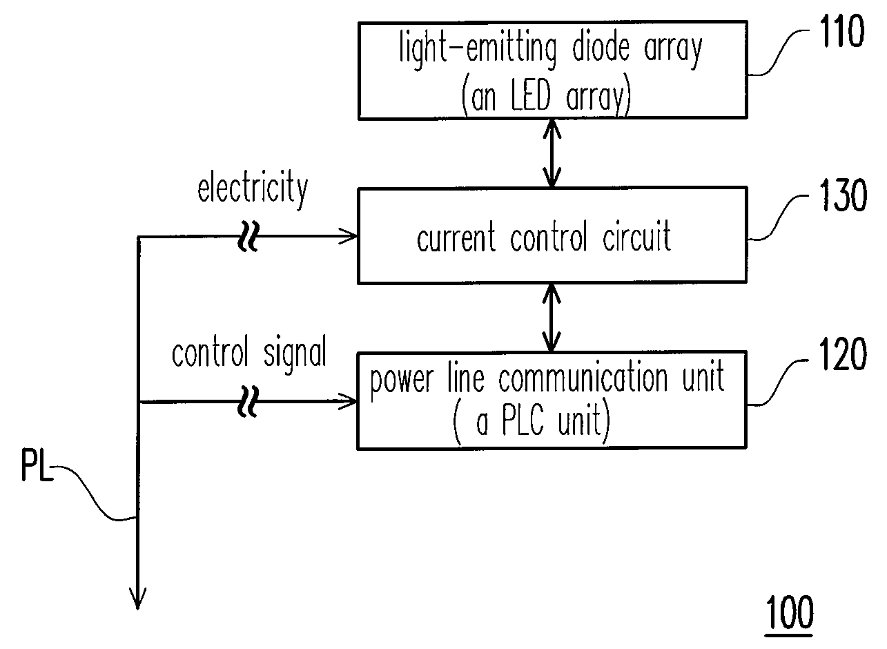
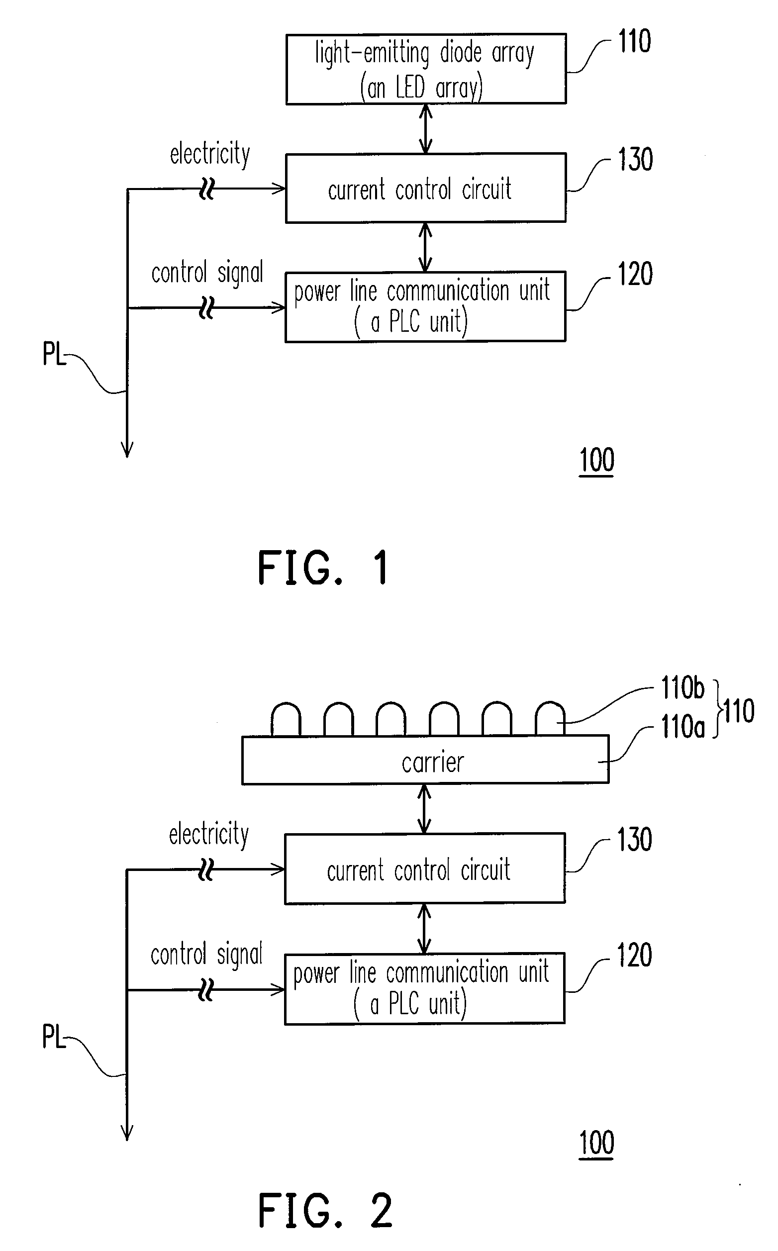
[0030]FIGS. 1 and 2 are schematic views illustrating a light emitting diode (LED) light source according to an embodiment of the present invention. Referring to FIG. 1, the LED light source 100 of the present invention includes an LED array 110, a power line communication (PLC) unit 120 and a current control unit 130. The current control unit 130 is electrically connected with a power line PL, the LED array 110 and the PLC unit 120. As shown in FIG. 1, the PLC unit 120 is connected with the power line PL, so as to receive a control signal transmitted from the power line PL. The PLC unit 120 controls the current control unit 130 to output a driving current to the LED array 110 according to the control signal, and thereby the LED array 110 can display determined brightness. Under some particular circumstances (e.g. an emergency), the PLC unit 120 even can control the current control unit 130 to output an over-driving current to the LED array 110, so that the LED array 110 can display ult
second embodiment
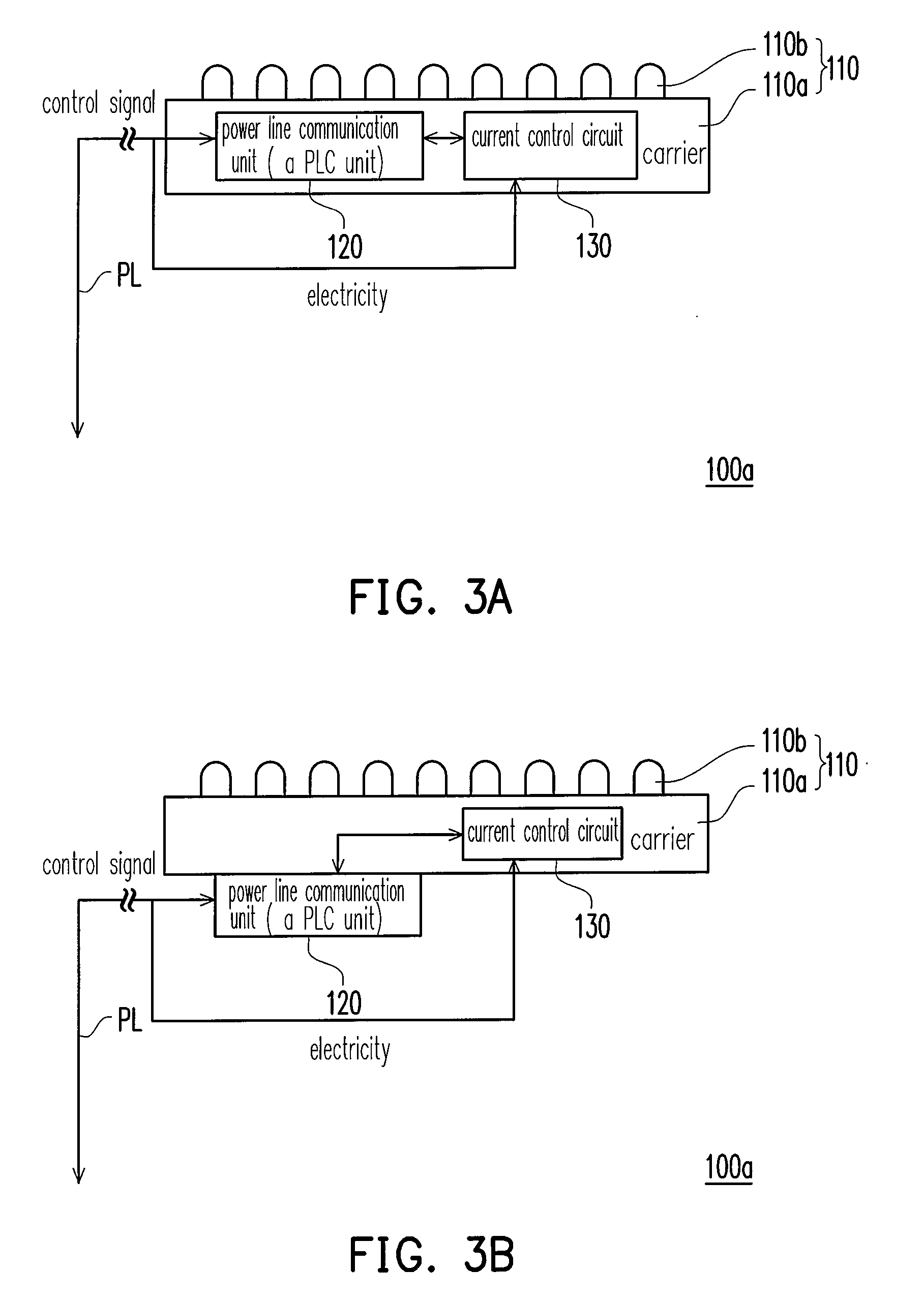
[0034]FIGS. 3A and 3B are schematic views illustrating an LED light source according to a second embodiment of the present invention. Referring to FIGS. 3A and 3B, since an LED array 110 according to the present embodiment is a COB type package, at least one of a PLC unit 120 and a current control unit 130 can be integrated in a carrier 110a (circuit board), and thereby the PCL unit 120 and the current control unit 130 are electrically connected to each other through the carrier 110a (circuit board). In other words, a designer can integrate the PLC unit 120 into the carrier 110a (circuit board) according to actual demands and dispose the current control unit 130 independently from the carrier 110a (circuit board). Of course, the designer can also integrate the current control unit 130 into the carrier 110a (circuit board) and dispose the PLC unit 120 independently from the carrier 110a (circuit board), as shown in FIG. 3B. Moreover, the designer can simultaneously integrate the PLC uni
third embodiment
[0036]FIG. 4 is a schematic view illustrating an LED light source according to a third embodiment of the present invention. Referring to FIG. 4, the LED light source 100b is similar to the LED light source 100 of the first embodiment. The main difference between the LED light source 100b and the LED light source 100 is that the LED light source 100b further comprises a wireless communication unit 140 and the wireless communication unit 140 is electrically connected with a PLC unit 120. According to an embodiment o the present invention, the wireless communication unit 140 includes an IEEE 802.15.4 ZigBee wireless communication unit or a worldwide interoperability for microwave access (WiMAX) wireless communication unit. Of course, the wireless communication unit 140 can also be a communication unit with other wireless communication protocols. The wireless communication unit 140 according to the present invention is not limited to the IEEE 802.15.4 ZigBee wireless communication unit or
PUM
 Abstract
Description
Claims
Application Information
 - R&D Engineer
- R&D Manager
- IP Professional
- Industry Leading Data Capabilities
- Powerful AI technology
- Patent DNA Extraction
Browse by: Latest US Patents, China's latest patents, Technical Efficacy Thesaurus, Application Domain, Technology Topic.
© 2024 PatSnap. All rights reserved.Legal|Privacy policy|Modern Slavery Act Transparency Statement|Sitemap