Video camera

a technology of video camera and video input, applied in the field of video camera, can solve problems such as increasing processing load

Inactive Publication Date: 2009-03-12
XACTI CORP
View PDF16 Cites 17 Cited by
  • Summary
  • Abstract
  • Description
  • Claims
  • Application Information

AI Technical Summary

Benefits of technology

The present invention relates to an imaging system that can automatically detect changes in brightness caused by objects being photographed without interrupting their view. This helps improve the quality of images taken through the system. It also allows for automatic adjustments to compensate for any variations over time due to factors like environmental conditions such as temperature and humidity. Overall, this technology improves the overall performance and functionality of the cameras used for taking pictures.

Problems solved by technology

The technical problem addressed by this patent is how to accurately detect if there are flips caused by lightning on a video camera due to different times during which the camera's exposure time period matches with the duration of the flashing lights used for photography.

Method used


Image

  • Video camera
  • Video camera
  • Video camera

Examples


Embodiment Construction

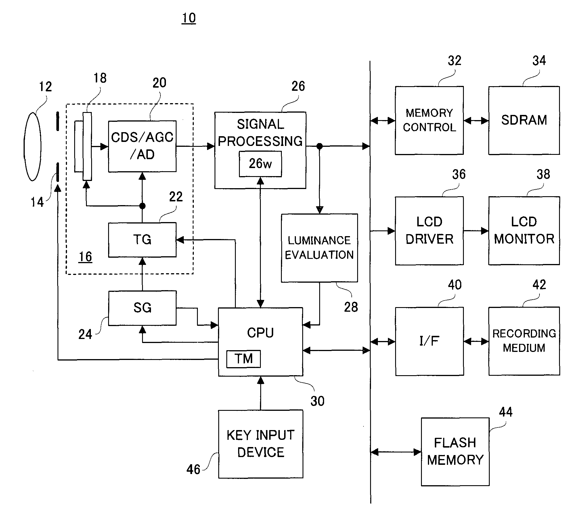
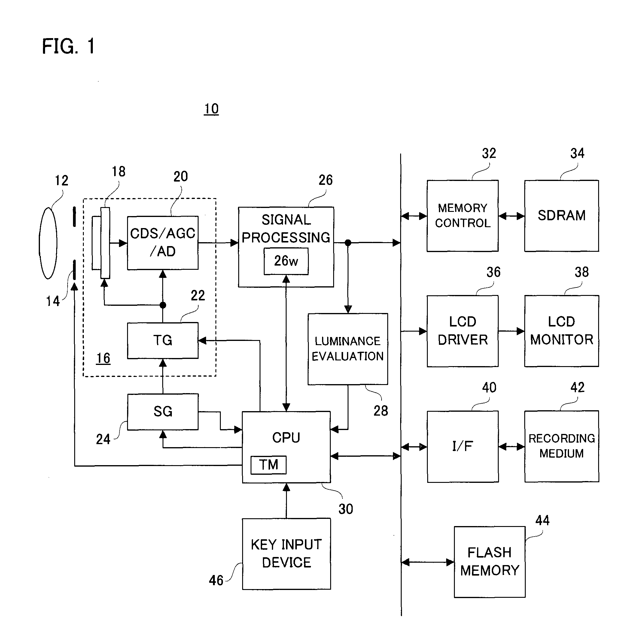
[0025]With reference to FIG. 1, a video camera 10 of this embodiment includes an optical lens 12 and an aperture unit 14. An optical image of an object scene through these members is irradiated onto a front surface, i.e., an imaging surface, of an imaging portion 18 configuring a CMOS-type image sensor 16, and is then photoelectrically converted. Thereby, a raw image signal formed of electric charges representing an object scene image is generated.

[0026]When a power supply is turned on, a CPU 30 instructs a TG Timing Generator) 22 configuring the image sensor 16 to repeatedly perform an exposure and an electric-charge reading-out. The TG 22 applies to the imaging portion 18 a plurality of timing signals responding to a vertical synchronization signal Vsync outputted from an SG (Signal Generator) 24 in order to repeatedly execute an exposure operation of the imaging surface and a reading-out operation of the electric charges obtained thereby. The vertical synchronization signal Vsync is


PUM


Abstract

An image sensor has an imaging surface irradiated with an optical image of an object scene, and repeatedly generates an object scene image. A CPU repeatedly determines whether or not a specific variation exceeding a reference is generated in the object scene captured by the image sensor, in parallel with a generating process of the object scene image by the image sensor. When a determination result is updated from a negative result to an affirmative result, the CPU waits for an elapse of a designated period, then, determines presence or absence of a generation of a flicker, and executes a flicker countermeasure process, as needed.

Description


Claims


Application Information

Patent Timeline
Owner XACTI CORP
Why Eureka
Try Eureka