Systems and methods for carrier ethernet using referential tables for forwarding decisions

Active Publication Date: 2009-06-04
CIENA
View PDF22 Cites 47 Cited by
  • Summary
  • Abstract
  • Description
  • Claims
  • Application Information

AI Technical Summary

Benefits of technology

[0012]In various exemplary embodiments, the present invention maintains current mechanisms of Ethernet addressing and QoS marking with the addition of specific referential tables. The referential tables are utilized for forwarding decisions based on any and/or multiple fields within the packets simultaneously, such as, for example, incoming port number, incoming MAC, incoming VLAN, outgoing MAC, outgoing VLAN, P-bits, Differentiated Services Code Point (DSCP), MPLS label,

Problems solved by technology

However, Ethernet is not quite robust enough for carrier transport applications.
Disadvantageously, all of the above described methods require prioritization to be marked in either the fo

Method used


Image

  • Systems and methods for carrier ethernet using referential tables for forwarding decisions
  • Systems and methods for carrier ethernet using referential tables for forwarding decisions
  • Systems and methods for carrier ethernet using referential tables for forwarding decisions

Examples


Embodiment Construction

[0022]In various exemplary embodiments, the present invention maintains current mechanisms of Ethernet addressing and QoS marking with the addition of specific referential tables. The referential tables are utilized for forwarding decisions based on any and / or multiple fields within the packets simultaneously, such as, for example, incoming port number, incoming MAC, incoming VLAN, outgoing MAC, outgoing VLAN, P-bits, DSCP, MPLS label, TCP / UDP port numbers, IP, SIP, HTTP, and the like. A user can define the forwarding criteria based on any combination / permutation fields in the packet. Advantageously, the present invention removes the need to introduce explicit tunnel labels in the Ethernet frame in order to maintain the desired QoS within the network removing explicit labeling requirements.

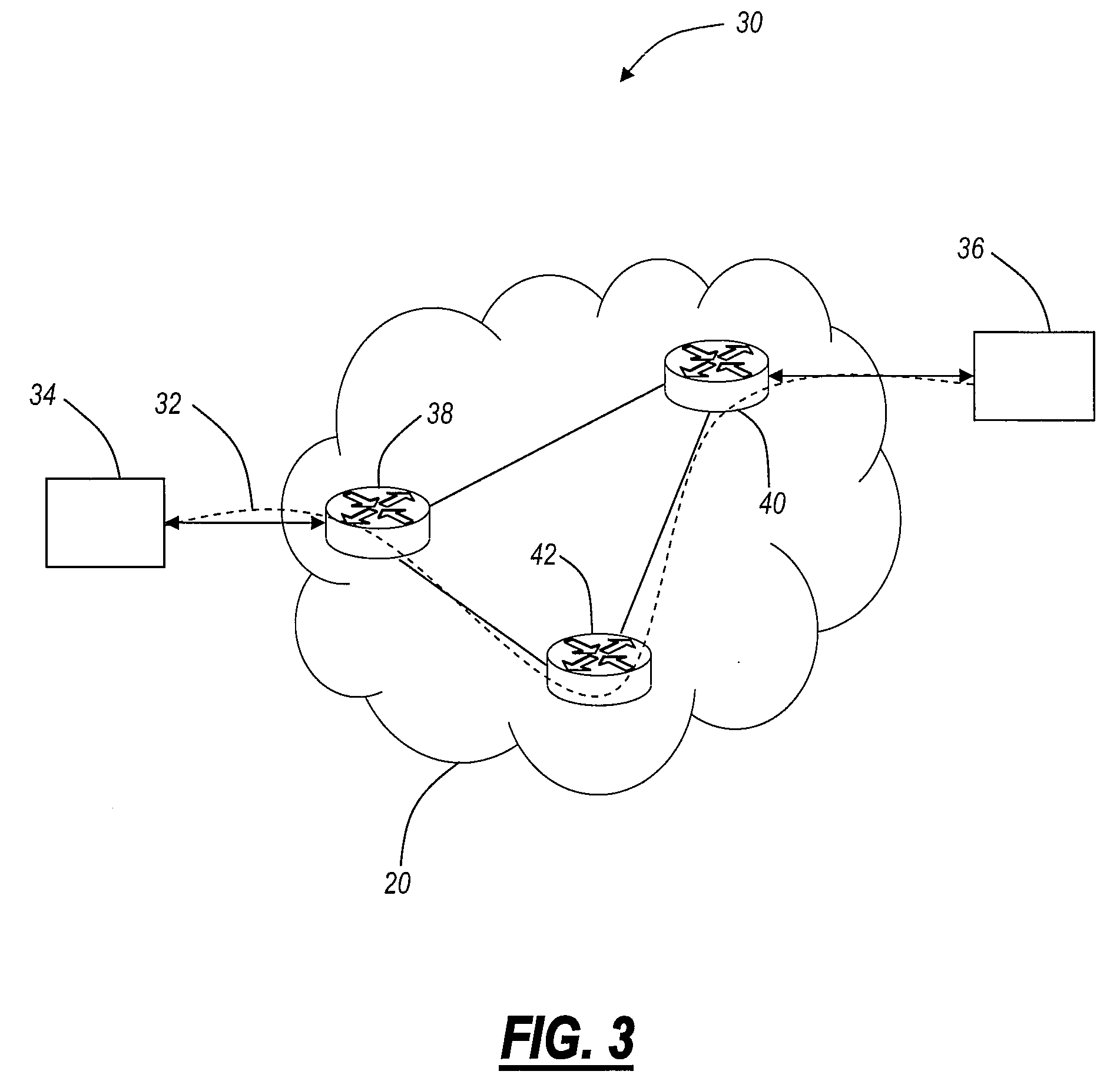
[0023]Referring to FIG. 3, a Carrier Ethernet network 30 is illustrated according to an exemplary embodiment of the present invention. The network 30 includes a connection 32 between clients 34


PUM


Abstract

The present invention utilizes specific referential tables for forwarding decisions while maintaining current mechanisms of Ethernet addressing and QoS marking. The referential tables are utilized for forwarding decisions based on any and/or multiple fields within the packets simultaneously, such as, for example, incoming port number, incoming MAC, incoming VLAN, outgoing MAC, outgoing VLAN, P-bits, DSCP, MPLS label, TCP/UDP port numbers, IP, SIP, HTTP, and the like. A user can define the forwarding criteria based on any combination/permutation fields in the packet. Advantageously, the present invention removes the need to introduce explicit tunnel labels in the Ethernet frame in order to maintain the desired QoS within the network removing explicit labeling requirements.

Description


Claims


Application Information

Patent Timeline
Owner CIENA
Why Eureka
Try Eureka