Vibration generator for a vibration pile driver

a technology of vibration generator and vibration pile, which is applied in the direction of mechanical vibration separation, bulkhead/pile, percussive tools portable, etc., can solve the problems of reducing the efficiency of the vibration generator, so as to reduce the power loss and energy-saving operation

Active Publication Date: 2009-07-30
ABI ANLAGENTECHN BAUMASCHEN INDBEBEDARF
View PDF9 Cites 10 Cited by
  • Summary
  • Abstract
  • Description
  • Claims
  • Application Information

AI Technical Summary

Benefits of technology

The technical effect of this patented design is improved efficiency when used with vibrating tools such as nail guns or screwdrivers due to reduced power loss caused by improper operating characteristics. This results from having balance weights attached at specific locations along certain parts of the tool's structure instead of just being fixedly connected together. By controllably changing these balancing weight positions, it becomes easier to operate efficiently without sacrificing performance.

Problems solved by technology

This patented describes different types of equipment called vibrators (vacuum cleaners). They use an oscillatory motion to remove debris on surfaces like roads during maintenance work. However, these machines have certain technical disabilities due to their design features. One important issue involves energy consumption caused when there's too much power needed while driving heavy loads over uneven terrain with varying levels of friction between the machine surface and its surroundings.

Method used


Image

  • Vibration generator for a vibration pile driver
  • Vibration generator for a vibration pile driver
  • Vibration generator for a vibration pile driver

Examples


Embodiment Construction

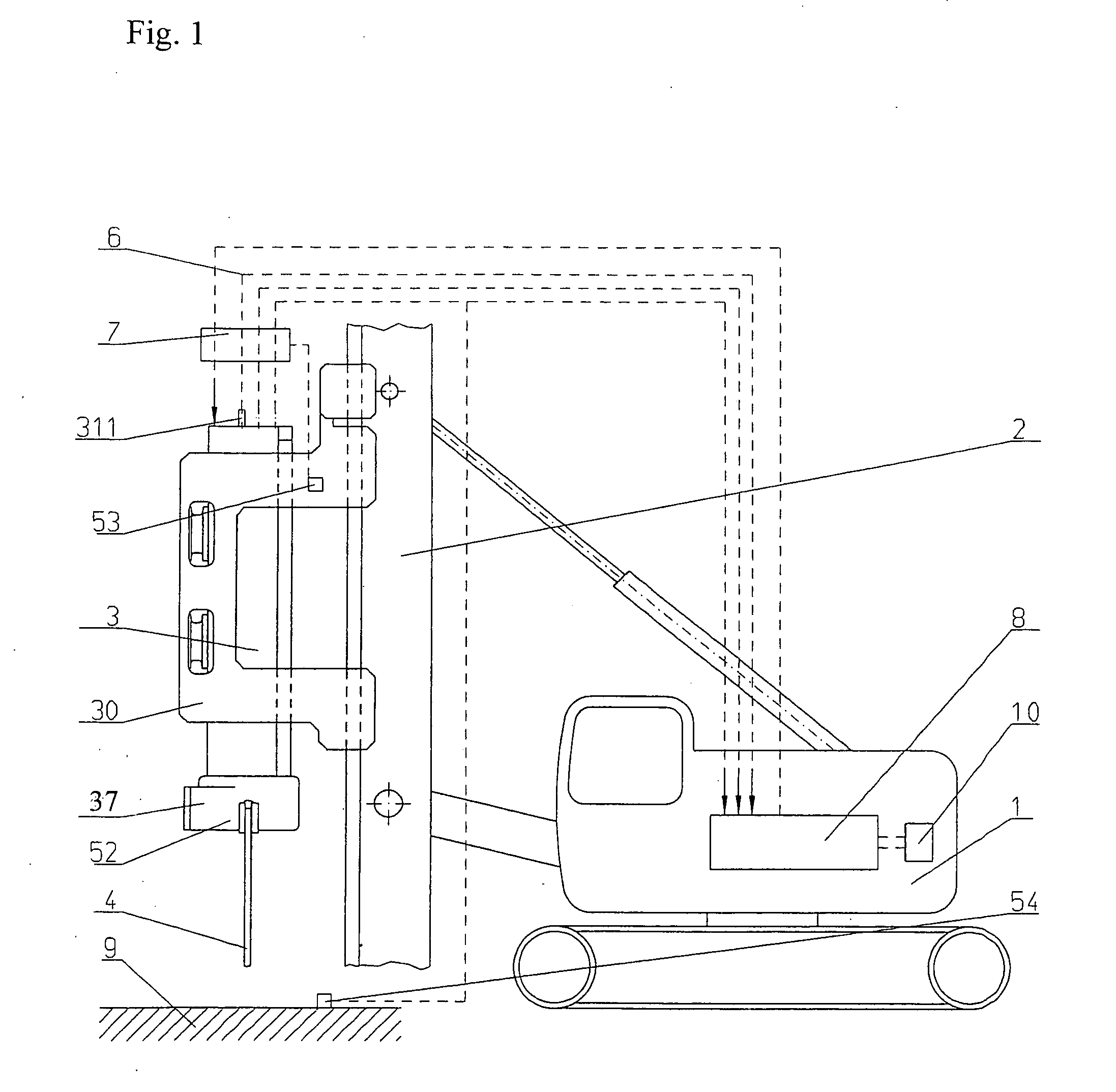
[0030]The vibration pile driver selected as an exemplary embodiment consists essentially of a support device 1, on which a vibration generator (vibrator) 3 is disposed so that it can be displaced vertically, by way of a mast 2. Vibration generator 3 comprises a housing 31, which is surrounded by a hood 30. Clamping pliers 37 for accommodating pile-driven material 4 are disposed on hood 30. Hood 30 serves to guide vibration generator 3, and transfers the static force of mast 2 to vibration generator 3. Vibration generator 3 generates a vibration, by way of rotating imbalances 3311, 3321, 3331, 3511, 3521, 3531, which vibration is transferred to material 4 to be pile-driven, by way of clamping pliers 37.

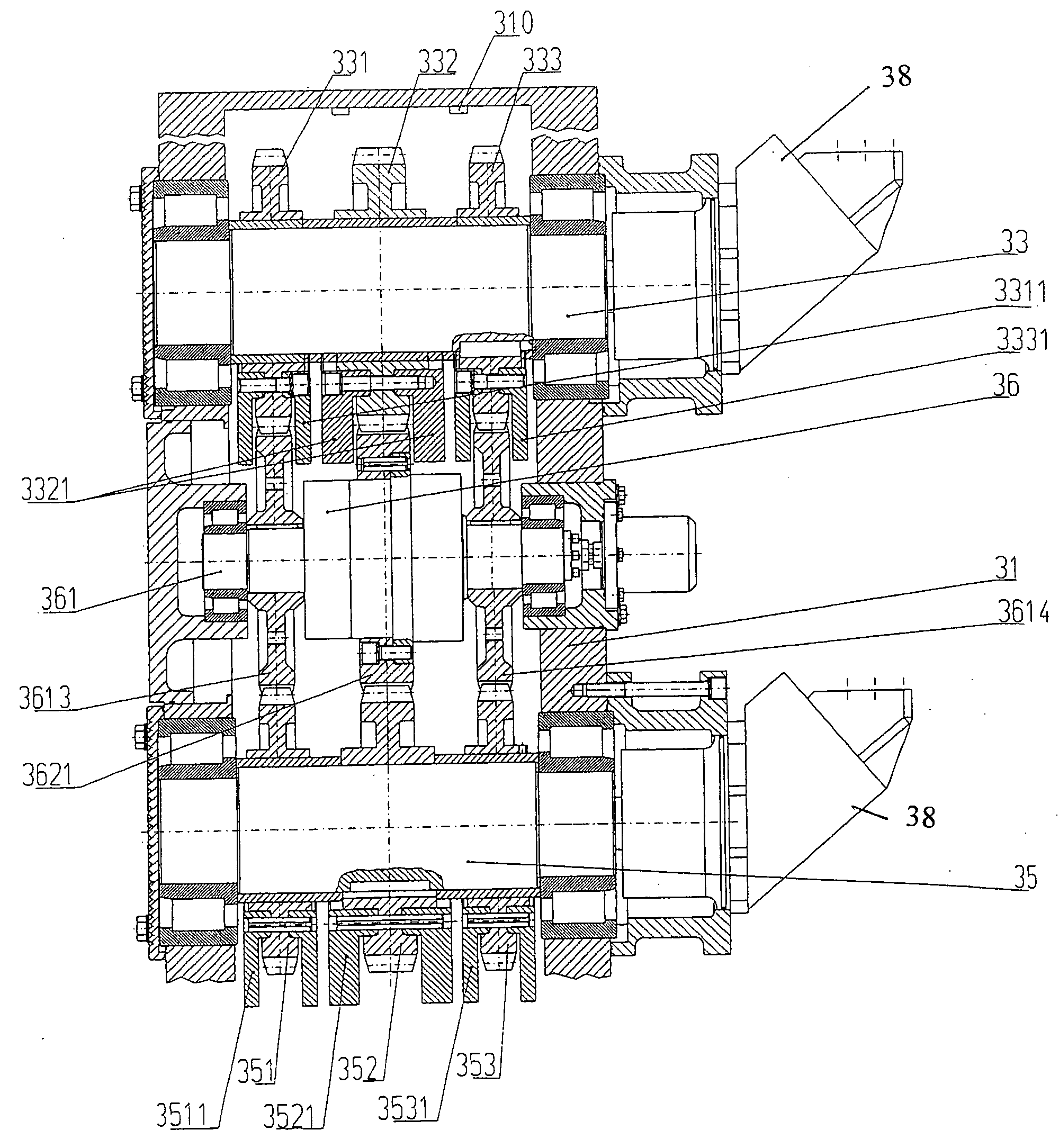
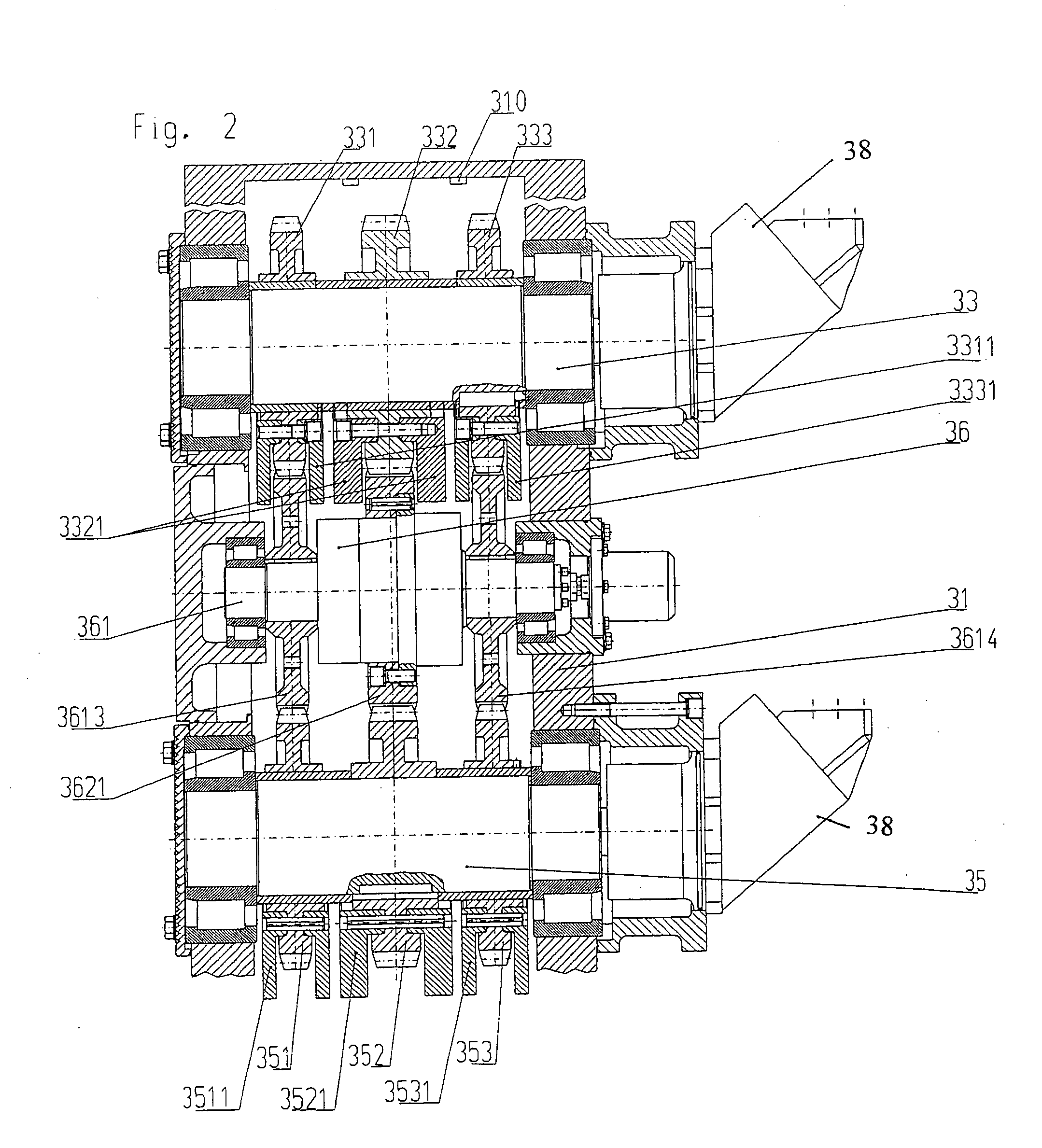
[0031]Vibration generator 3 is structured as a vibrator gear mechanism (FIG. 2). It consists essentially of a housing 31, in which shafts 33, 35 provided with gear wheels 331, 332, 333, 351, 352, 353 are mounted to rotate. Gear wheels 331, 332, 333, 351, 352, 353 are each provided with im


PUM


Abstract

A vibration generator for a vibration pile driver has imbalance masses that can rotate and which are disposed on shafts. The rotational position of the imbalance masses can be adjusted relative to one another. A control and regulation circuit is provided, which has the following components: a memory unit for storing ground composition data sets or task-specific default data sets with defined operational characteristic variables; sensors for continuous detection of the defined operational characteristic variables; an evaluation unit for comparing the operational characteristic variables that are determined with the operational characteristic variables of the selected default data set; a regulation device for regulating the vibration generator; and a control device for controlling the means for adjusting the rotational position of the imbalance masses relative to one another. The vibration generator is part of a vibration pile driver.

Description


Claims


Application Information

Patent Timeline
Owner ABI ANLAGENTECHN BAUMASCHEN INDBEBEDARF
Why Eureka
Try Eureka