Holographic display devices

a technology of optical systems and display devices, applied in the field of optical systems for holographic projectors, can solve problems such as inability to achiev

Inactive Publication Date: 2009-08-20
LIGHT BLUE OPTICS
View PDF5 Cites 38 Cited by
  • Summary
  • Abstract
  • Description
  • Claims
  • Application Information

AI Technical Summary

Benefits of technology

The present technology allows for improved display quality when displaying images on devices like virtual reality headsets due to its ability to change the amount of visible light transmitted through it based upon factors like ambient brightness levels. This can improve how well users see things clearly even at long distances while also improving overall visual experience during playback sessions.

Problems solved by technology

The technical problem addressed by these inventors relates how to create an even bigger or more visible image on smaller displays without making them bulky due to their use of lenses that require large amounts of light energy.

Method used


Image

  • Holographic display devices
  • Holographic display devices
  • Holographic display devices

Examples


Embodiment Construction

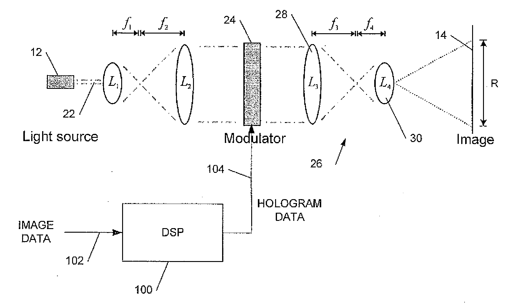
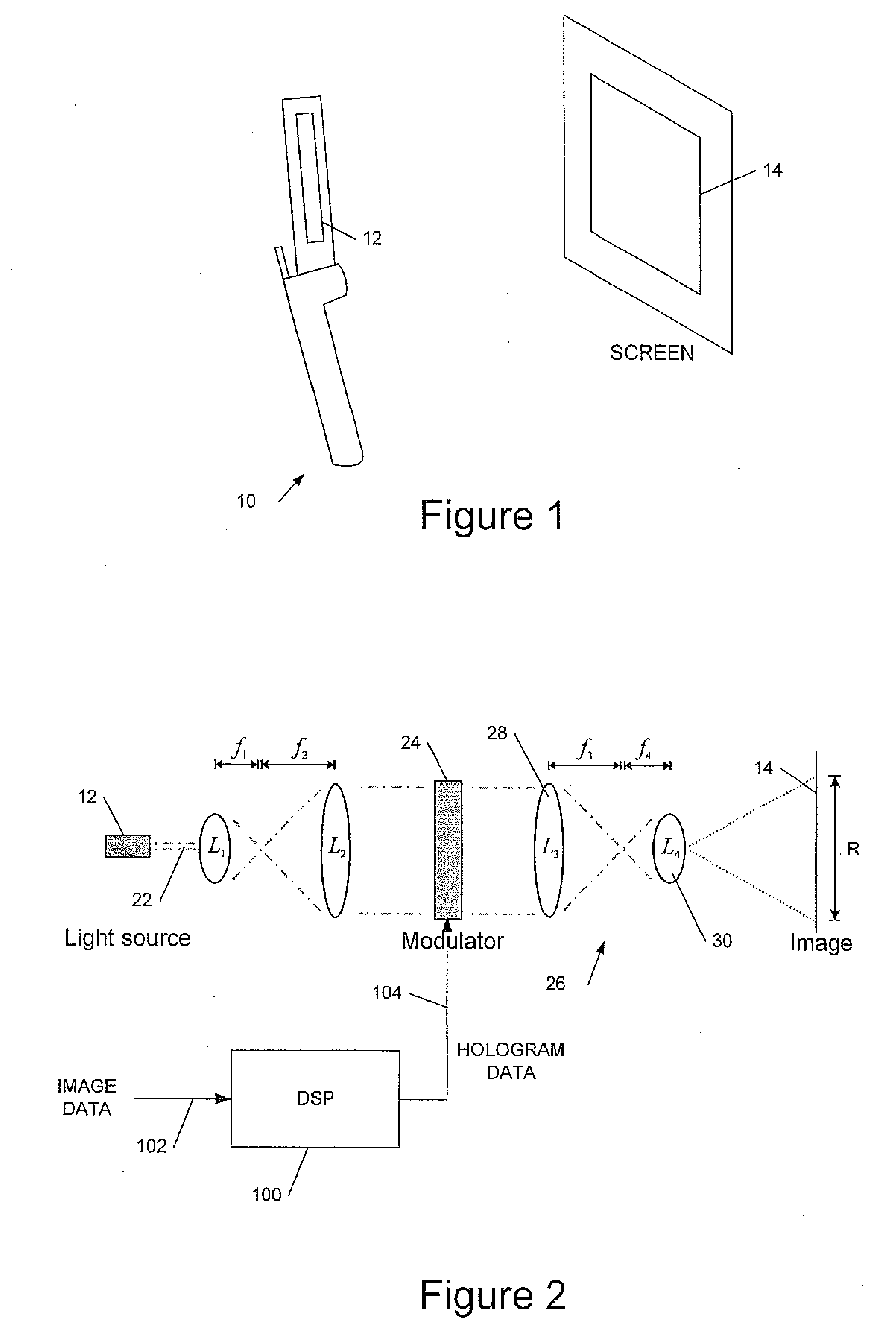
[0032]We have previously described, in UK patent application number 0512179.3 filed 15 Jun. 2005, incorporated by reference, a holographic projection module comprising a substantially monochromatic light source such as a laser diode; a spatial light modulator (SLM) to (phase) modulate the light to provide a hologram for generating a displayed image; and a demagnifying optical system to increase the divergence of the modulated light to form the displayed image. Absent the demagnifying optics the size (and distance from the SLM) of a displayed image depends on the pixel size of the SLM, smaller pixels diffracting the light more to produce a larger image. Typically an image would need to be viewed at a distance of several metres or more. The demagnifying optics increase the diffraction, thus allowing an image of a useful size to be displayed at a practical distance. Moreover the displayed image is substantially focus-free: that is the image is substantially in focus over a wide range or a


PUM


Abstract

This invention relates to optical systems for holographic projectors. We describe a holographic image projection system, the system including: a spatial light modulator (SLM) for displaying a hologram; first optics to provide an input beam to said SLM; second optics to process an output beam from said SLM to provide a displayed image; and a hologram processor to receive image data for display and to output data to said SLM to display a hologram to provide said displayed image; and wherein at least one lens of said first optics or said second optics is encoded in said hologram.

Description


Claims


Application Information

Patent Timeline
Owner LIGHT BLUE OPTICS
Why Eureka
Try Eureka