Removal Method and Removal Apparatus for Entrained Air in Coating Fluid

a technology of entrapment air and removal apparatus, which is applied in the direction of liquid degasification, separation processes, instruments, etc., can solve the problems of high cost of photochromic fluid and the problem of large expenditure, and achieve the effect of preventing backflow

Inactive Publication Date: 2009-09-17
TOKUYAMA CORP
View PDF2 Cites 8 Cited by
  • Summary
  • Abstract
  • Description
  • Claims
  • Application Information

AI Technical Summary

Benefits of technology

The technical effect that this new device described by this inventor solves with its use is how it removes unwanted gas from coatings during manufacturing processes without affecting their quality level. This means they are more reliable than older methods like vacuum degassers due to less frequent maintenance needed compared to traditional techniques such as evaporation pumps.

Problems solved by technology

Technological Problem: Current techniques used to remove impurity particles during production involve adding liquid called photochromism into certain areas where they were previously unimaged. However, these solutions have drawbacks like causing unwanted deposits due to residual solvents left behind after processing. Additionally, current processes require multiple steps involving evaporation/cooling, leading to increased costs associated therewith.

Method used


Image

  • Removal Method and Removal Apparatus for Entrained Air in Coating Fluid
  • Removal Method and Removal Apparatus for Entrained Air in Coating Fluid
  • Removal Method and Removal Apparatus for Entrained Air in Coating Fluid

Examples


Embodiment Construction

[0041]An embodiment of a removal method for entrained air in a coating fluid according to the present invention will now be described with reference to the accompanying drawings.

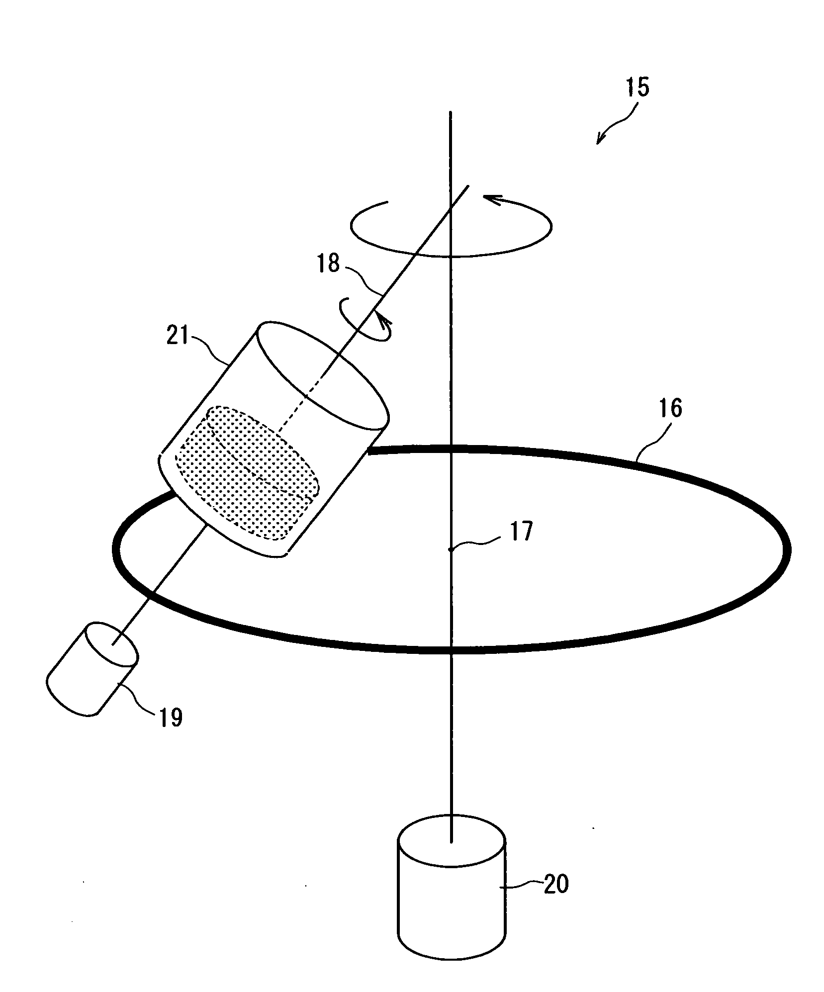
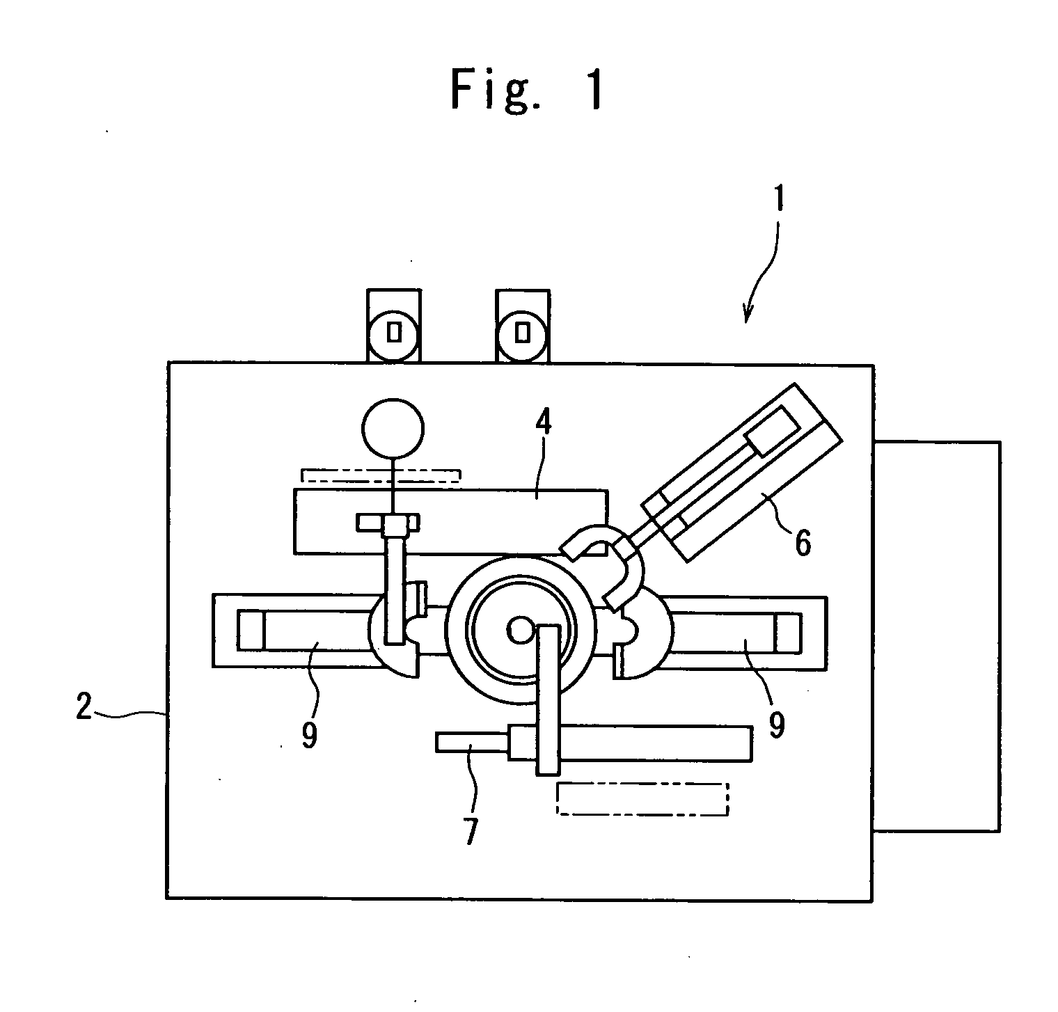
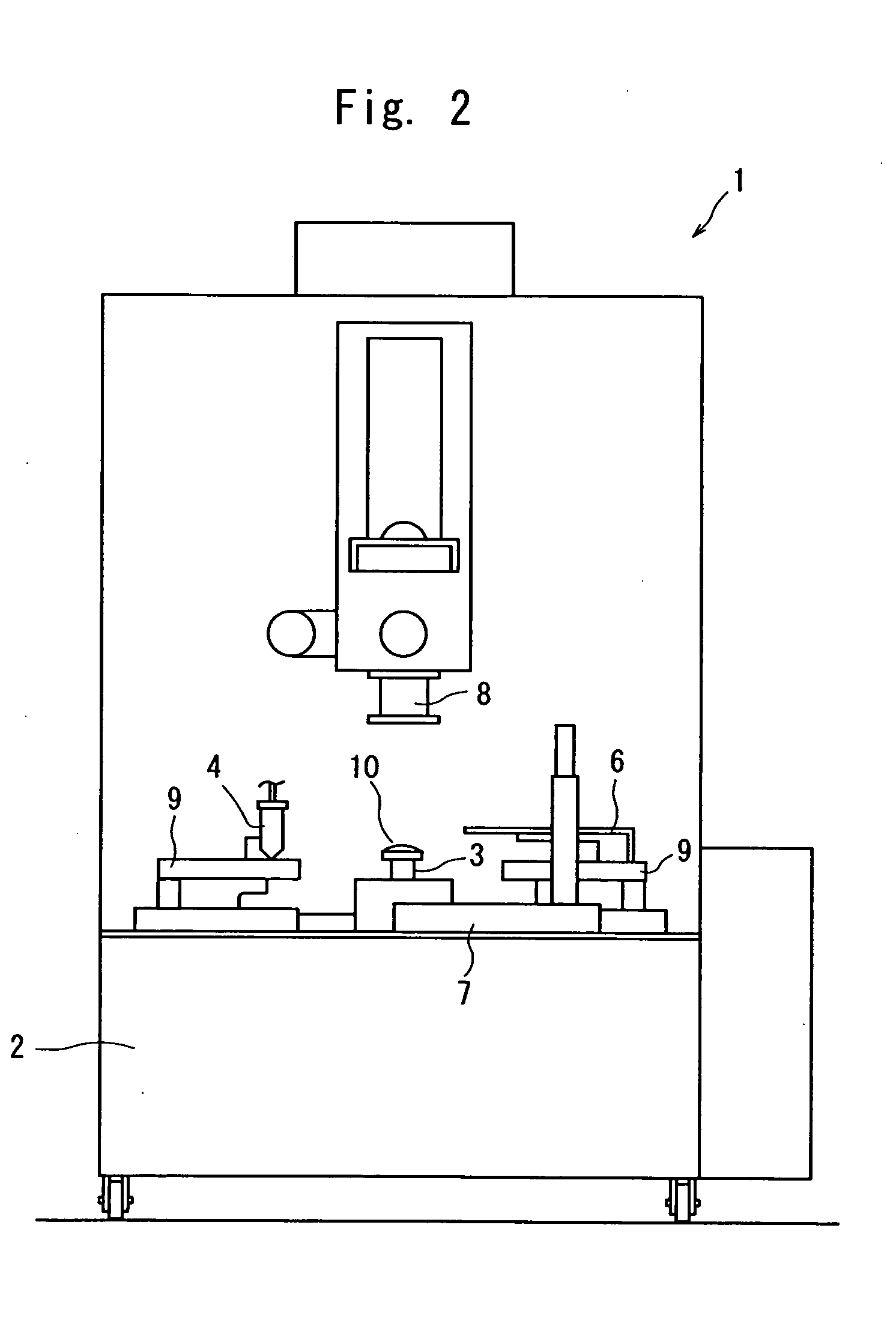
[0042]FIGS. 1 and 2 show a photochromic coating apparatus for coating a photochromic fluid onto a lens under automatic control. The lower side of the photochromic coating apparatus in FIG. 1 is the front side of the apparatus (in the Y-axis direction), and the right-to-left side of the apparatus is in the lateral direction (X-axis direction).

[0043]A photochromic coating apparatus 1 has a lens support device 3, a coating unit support device 4, a lens height measuring sensor 6, a coating film uniformizing device 7, a UV device 8, and a movable fluid receiving device 9 provided on a base stand 2.

[0044]As shown in FIG. 3, the lens support device 3 is provided in a nearly central portion of the base stand 2, and has a circular pedestal 31 formed to protrude upward from the base stand 2. A guide member 32 is provided


PUM

PropertyMeasurementUnit
Thicknessaaaaaaaaaa
Speedaaaaaaaaaa
Photochromicaaaaaaaaaa

Abstract

The present invention has as an object to render a photochromic coating layer free from air bubbles and obtain a uniform layer without film thickness unevenness in the coating layer. In the prevent invention, entrained air in a coating fluid stored in a vessel of a coating unit comprising the vessel, a check valve for preventing back-flow of the coating fluid connected to the vessel, and optionally an ejection nozzle connected to the check valve; air existing inside of the check valve; and optionally air existing inside of the ejection nozzle are removed by plugging an outlet of the coating fluid existing downstream of the check valve and then rotating the coating unit on an axis of the vessel and orbiting the coating unit on a revolution axis simultaneously.

Description


Claims


Application Information

Patent Timeline
Owner TOKUYAMA CORP
Why Eureka
Try Eureka