Orbital Sign Assembly

Inactive Publication Date: 2009-10-08
MCCOY VANCE
View PDF15 Cites 0 Cited by
  • Summary
  • Abstract
  • Description
  • Claims
  • Application Information

AI Technical Summary

Benefits of technology

[0015](e) allowing free motion of the sign bracket and sign under high wind conditions like those fou

Problems solved by technology

The disadvantage to this system is that when the wind blows, it transfers torque directly to the span wire since it is rigidly attached.
This will eventually result in damage, loosening, and unbundling of associated electrical, traffic signal cables and vehicle detection cables.
In a worst case scenario, the span wire can break causing all of the attached traffic signals and signage to fall onto the roadway.
This 180 degree ran

Method used


Image

  • Orbital Sign Assembly
  • Orbital Sign Assembly
  • Orbital Sign Assembly

Examples


Embodiment Construction

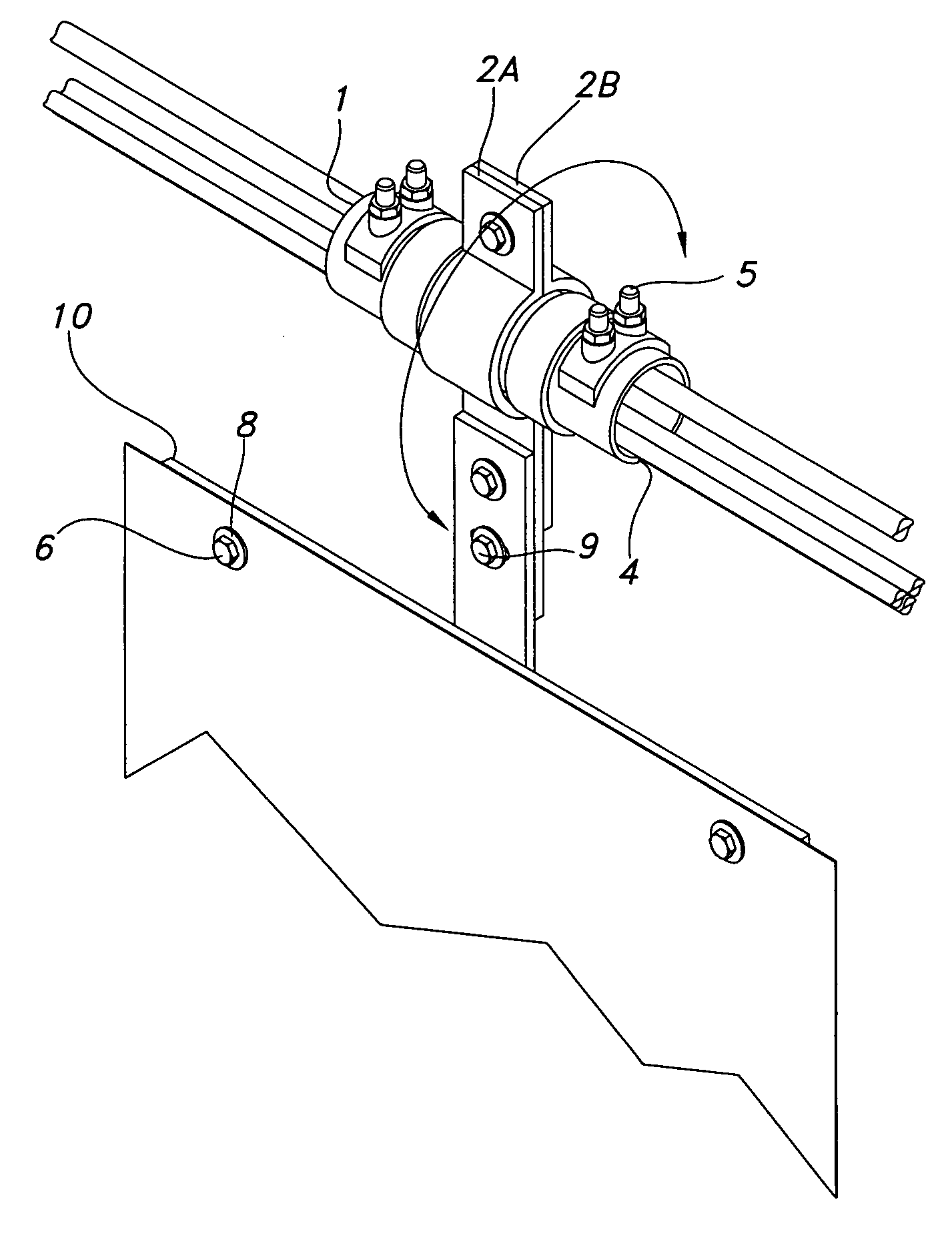
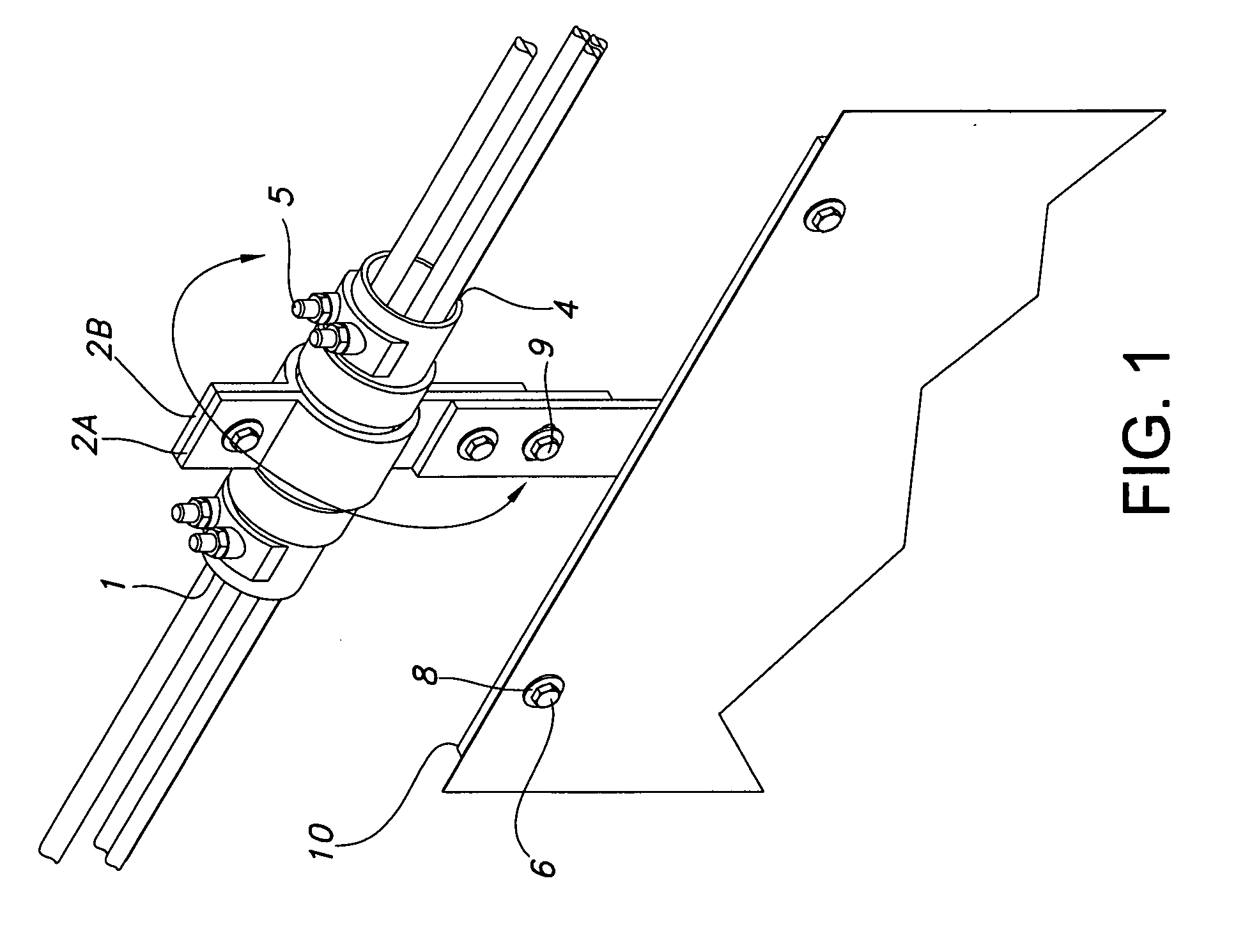
[0024]FIG. 1 shows a perspective view of the preferred embodiment of the orbital sign assembly. The orbital sign assembly includes mainly a cable saddle 1, a pivot attachment 2, and a sign bracket 10. The cable saddle is cylindrical in shape and acts as a bearing or chassis to which the pivot attachment attaches. The pivot attachment 2 is comprised of two pieces 2a and 2b which are joined together at top and bottom. The pivot attachment 2 has two semicircle sections that when joined form a circular opening that allows for the cable saddle 1 to be enclosed about. The pivot attachment 2 has two ends. At one end there is the above mentioned circular opening and at the other an attachment point for the sign bracket 10.

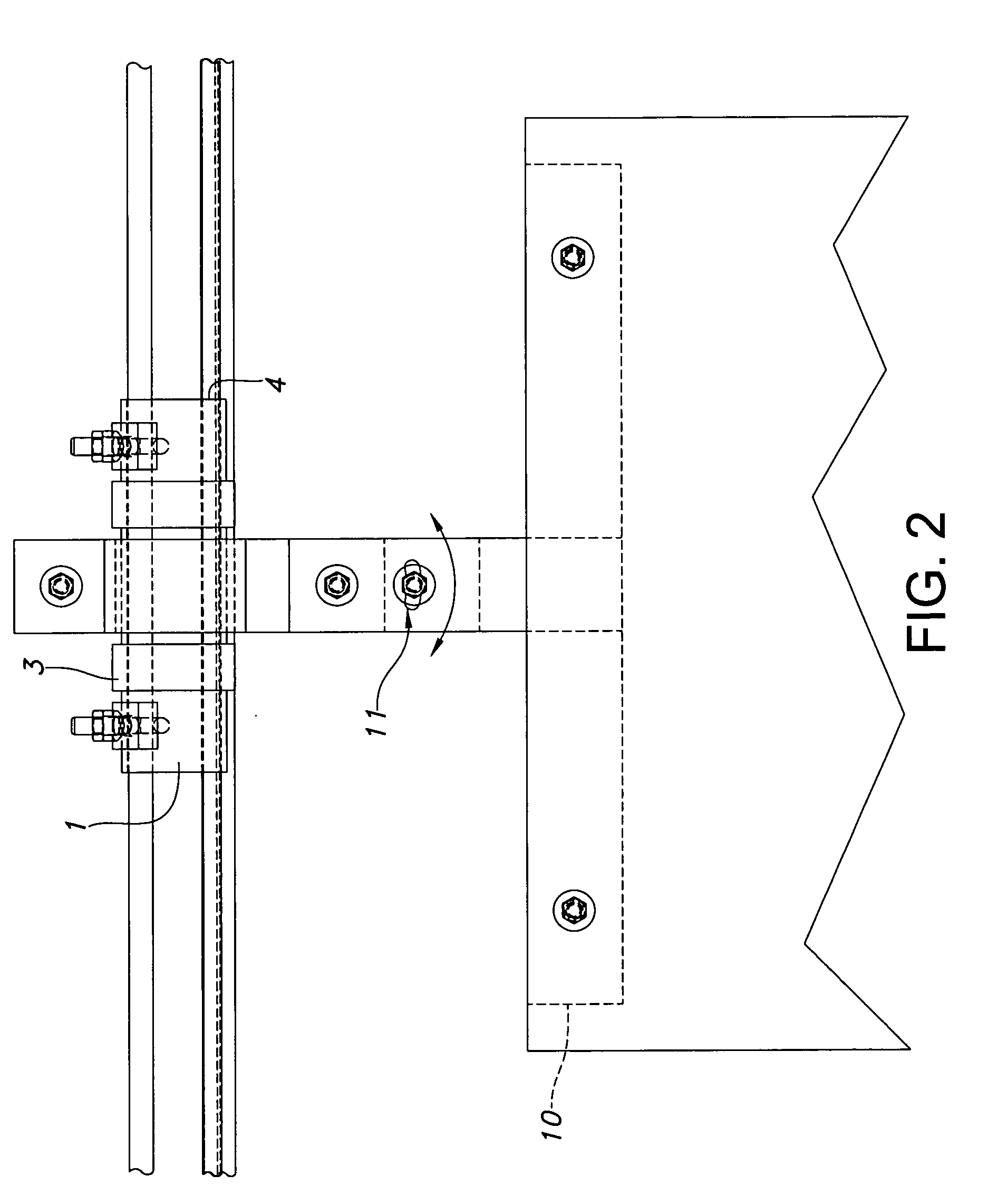
[0025]The cable saddle 1 (FIG. 1) as previously stated, is cylindrical in shape and includes two rings, guides, or pivot attachment rails 3 (FIG. 2). The pivot attachment rails 3 are raised above the contour of the cable saddle and spaced appropriately to accommodate the pivo


PUM


Abstract

One embodiment of an orbital sign assembly, allowing for attachment to and full pivot or orbit capability of the attached signage around a horizontal run of span wire or other support member. Any one traffic signage is supported from a horizontal run of a span wire or other support member by a orbital sign assembly comprising a sign bracket (10) with attachment points at opposing ends and center, a pivot attachment (2) allowing 360 degree pivoting of the sign, which adjoins the sign bracket (10) to the a cable saddle (1) which contains two pivot attachment rails (3) for limiting side to side movement of the pivot attachment on its track. Conventional U-bolts (5) are located within the cable saddle and are used to clamp down to the span wire while still allowing traffic signal cables to be inserted through a cable slot (4) within the cable saddle (1). A cant tilt slot (11) is located on the sign bracket for leveling signage.

Description


Claims


Application Information

Patent Timeline
Owner MCCOY VANCE
Why Eureka
Try Eureka